Get the topology right
before transferring data
The Surface Edit > Stitch tools in Alias create a valid solid model topology.
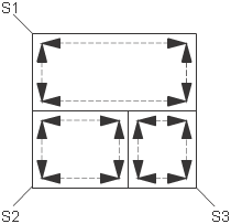
The following illustration shows three individual surfaces (labeled S1, S2, and S3). The edges of each surface are represented by dashed lines.

When models are constructed using the Alias advanced surface tools (Swept, Rail Surface and Square), it is common to create a number of smaller surfaces along the edge of one larger surface. This modeling technique does not create the twin edges required for a solid model. Stitching adds this information.