Displays information about the network, allows inspection of curve segments and sculpt curves, and recommends fixes for problems with continuity.
 .
.
The Analyze network tool displays information about components of the current curve network.
The Analyze network tool labels the curve network with the following information:
| Network component | Indicated by |
|---|---|
| Intersections | Red dots |
| Continuity type for each curve segment | Label at the midpoint of the curve segment (Pos or Tan). |
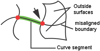
| Curve segments with at least one adjacent surface | White lines |
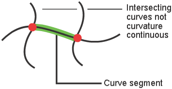
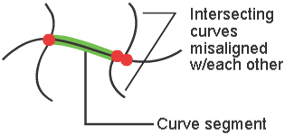
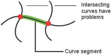
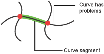
| Curve segments with no adjacent surfaces | Green lines |
| Sculpt curves | Red lines |
| Pinned curve segments | Pin icon |
The Analyze network tool also lets you select curve segments and sculpt curves to get specific information:
| Information | Description |
|---|---|
| Curve Type | Network or Sculpt. |
| Region of Influence(for sculpt curves) | Large, Medium, or Small. |
| Nature | Pinned or Free.Whether or not the surface is pinned to the curve segment. |
| Edge Type | Interior: the curve segment is inside the network (the surfaces are on both sides of the segment).Boundary: the curve segment is on the edge of the network (the surfaces are only on one side of the segment).Orphan: the curve segment is not connected to any surface at all. |
| Continuity | Achieved or Not achieved.If continuity was not achieved, the Analyze network tool will give a recommended action. |
| Recommended Action(for curve segments where continuity was not achieved) | A recommendation for how to modify the network so that the curve network can achieve the requested continuity. |
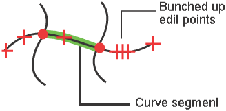
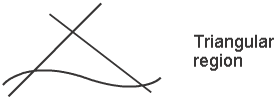
If the curve network could not achieve the requested continuity at a particular curve segment, the Analyze network tool will recommend a course of action to fix the problem and achieve the requested level of continuity: