Autodesk® ViewCube® navigation tool and NavBar provide the same viewing functionality found in the View Panel.
Overview of ViewCube and NavBar
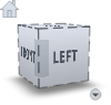
The ViewCube tool is a persistent, clickable and draggable interface that you use to switch between standard and isometric views of your model. By default, it displays in the top right corner of the perspective window in an inactive state. While the ViewCube tool is inactive, it provides visual feedback about the current viewpoint as view changes occur. When you position the cursor over the ViewCube tool, the tool becomes active; you can switch to one of the available preset views, roll the current view, or change to the Home view of the model.
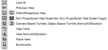
The NavBar is a tool panel associated with Autodesk® ViewCube®. It provides supplemental navigation functions that correspond with functionality on the View Panel.
Use the ViewCube and NavBar view control
The ViewCube displays by default, but you can use either the ViewCube tool and NavBar, or the View Panel to control your view, or you can choose to use neither.
To select the view control
To display the NavBar
 +
+  (Windows) or + Command
  (Mac).
To make the ViewCube active
Reorient the view with ViewCube
Use ViewCube to reorient the current view of a model. You can reorient the view with the ViewCube tool by clicking predefined areas to set a preset view as current, click and drag to freely change the view angle of the model, and define and restore the Home view.
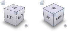
The ViewCube tool provides twenty-six defined areas you can click to change the current view of a model. The twenty-six defined areas are categorized into three groups: edge, corner, and face. Of the twenty-six defined areas, six of the areas represent standard orthogonal views of a model: top, bottom, front, back, left, and right. Orthogonal views are set by clicking one of the faces on the ViewCube tool.
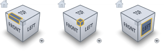
Use the other twenty defined areas to access angled views of a model. Clicking one of the corners on the ViewCube tool reorients the current view of the model to a three-quarter view, based on a viewpoint defined by three sides of the model. Clicking one of the edges reorients the view of the model to a half view based on two sides of the model.
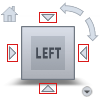
When you view a model from one of the face views, two roll arrow buttons display near the ViewCube tool. Use the roll arrows to rotate the current view 90 degrees clockwise or counterclockwise around the center of the view.
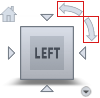
When the ViewCube tool is active while viewing a model from one of the face views, four orthogonal triangles display near the ViewCube tool. Use these triangles to switch to one of the adjacent face views.
You can also click and drag the ViewCube tool to reorient the view of a model to a custom viewpoint other than one of the twenty-six predefined viewpoints. As you drag, the cursor changes to indicate that you are reorienting the current view of the model. If you drag the ViewCube tool close to one of the preset orientations and it is set to snap to the closest view, the ViewCube tool rotates to the closest preset orientation.
The outline of the ViewCube tool helps you identify the form of orientation it is in: freeform or constrained. When the ViewCube tool is in freeform orientation, not orientated to one of the twenty-six predefined views, its outline displays dashed. The ViewCube tool is outlined in a solid continuous line when it is constrained to one of the predefined views.
Define and restore the Home view
The Home view is a special view stored with a model that makes it easy to return to a known or familiar view. You can define any view of the model as the Home view. Apply the saved Home view to the current view by clicking the Home button above the ViewCube tool.
The default Home position is the existing orientation of the default 3D view.
Define a view of the model as the Home view to allow you to easily return to that view by clicking the Home icon.
The ViewCube tool supports three different view projections: perspective, orthographic, and perspective with orthographic faces. When you change the view for a model, the view updates using the selected projection mode.
To change the view projection mode
Control the appearance and behavior of ViewCube
The ViewCube tool displays in one of two states: inactive and active. When the ViewCube tool is inactive, it appears partially transparent by default so that it does not obscure the view of the model. When active, it is opaque and may obscure the view of the objects in the current view of the model.
In addition to controlling the inactive opacity level of the ViewCube tool, you can also control the size and position of the tool:
To control the appearance of the ViewCube tool
When the cursor is in the vicinity of the ViewCube, the cube and all the additional controls are displayed, fully opaque. However, when the cursor is distant from the ViewCube, the additional controls (except the Home button) do not display; the ViewCube and the Home button may display at reduced opacity. Set the opacity display when the cursor is distant (inactive) from the ViewCube.
Select this option to maintain the up direction of the scene.
While being dragged, the ViewCube and the model rotate. If Snap to closest view is selected, the viewpoint will snap to one of the fixed views when it is angularly close to one of the fixed views.


 , and drag in the direction that
you want to orbit the model.
, and drag in the direction that
you want to orbit the model.