


Tutorial: using the Transformer
Rig tool to change the roof of a car
In this tutorial, you will learn how to use the Transformer Rig to change the roof of a car to give it a different centerline.
Part 1: Setting up the rig by adding targets and constraints
In this part of the tutorial, you will learn how to set up a rig to modify the roof of the car. Specifically, you will learn how to associate existing surfaces of this model as target and constraint surfaces in a rig.
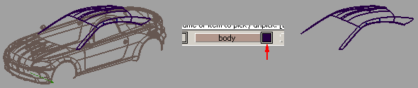
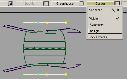
We only need to work with the surfaces of the greenhouse.
 to open the top view at
full size.
to open the top view at
full size.
 and draw a pick-box around
the middle surfaces as shown in the figure, and click Accept
Targets to select the roof surfaces as target geometry
in the rig.
and draw a pick-box around
the middle surfaces as shown in the figure, and click Accept
Targets to select the roof surfaces as target geometry
in the rig.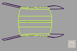
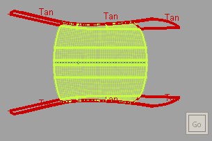
The word Tan means the constraints are all tangential constraints. The pale green dots that appear inside the target surfaces are part of the clamp visualization, and the color indicates that the target surfaces are free to be modified in the current rig.
In the Transformer Rig, any existing geometry can be used as modifiers or constraints. You can also create geometry to use as modifiers or constraints. You will do so in Part 2 of this tutorial.
 to leave the Transformer
Rig toolbox for now.
to leave the Transformer
Rig toolbox for now.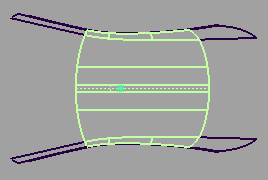
The target surfaces are
picked, and they have history. History for Transformer Rig is created
immediately after you have picked the initial set of surfaces as
targets. Whenever you wish to re-enter the Transformer Rig tool
to edit the rig, use Object Edit > Query Edit  and click with the on any of the target surfaces.
Part 2: Create a new surface to use as the modifier
In this part of the tutorial, you will learn how to create a surface that will be used as a modifier for the rig you have created in Part 1. You will be shown how to create a modifier surface customized for the targets in the rig, and also customized for the modification in mind.
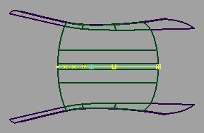
 . Use the and click on the dashed
line in the center of the middle surface of the roof.
. Use the and click on the dashed
line in the center of the middle surface of the roof.
You have just duplicated the centerline of the roof.
 , drag the curve down to
below the A pillar, as shown in the figure. Leave the curve picked.
, drag the curve down to
below the A pillar, as shown in the figure. Leave the curve picked. 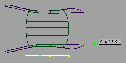
 ❒, to open the option window of the Mirror
Duplicate function.
❒, to open the option window of the Mirror
Duplicate function.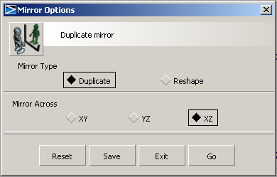
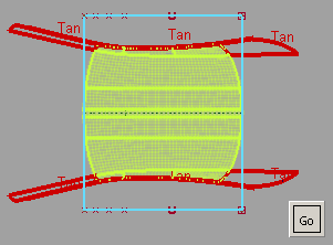
Make sure XZ is set. Click Go.
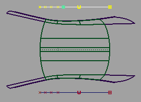
The curve is now duplicated and the new copy appears above the A and B pillars.
to click on the bottom curve
so that both curves are picked.
 to create a new layer. Name
the layer Curves.
to create a new layer. Name
the layer Curves.
 . Click the bottom curve,
then the top curve. A new surface is created.
. Click the bottom curve,
then the top curve. A new surface is created.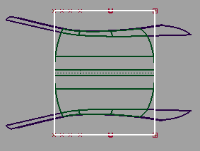
 . Click Yes in
the dialog that warns you about deleting history on active objects.
. Click any target surface
of the greenhouse to re-enter the Transformer Rig tool.
. Click Yes in
the dialog that warns you about deleting history on active objects.
. Click any target surface
of the greenhouse to re-enter the Transformer Rig tool.
The green and red visual highlights reappear. This indicates that you have returned to editing the rig that you have set up in Part 1 of this tutorial.
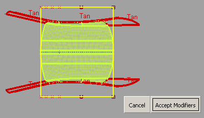
Click Accept Modifiers to confirm.
to leave the Transformer
Rig tool.
Now that we have completed the set-up of the rig, this part of the tutorial will show you how to use regular Alias functionality to make changes to the modifier geometry. Through Transformer Rig history updates, the target geometry (the roof surfaces) will update accordingly. This shows you the power of the Transformer Rig — your update to a single simple surface will update multiple surfaces in unison.
In this case we will use the Move CVs and Hulls tool, located at the bottom of the modeling control panel. You are free to use whichever tool you are comfortable with to change the modifier surface.
, and use the to pick the modifier surface.
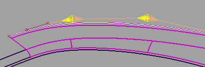
 , followed by Pick > Point Types > CV
  . Switch to the Side view,
and pick the two topmost CVs. This actually corresponds to two
rows of CVs of the modifier surface.
. Switch to the Side view,
and pick the two topmost CVs. This actually corresponds to two
rows of CVs of the modifier surface.
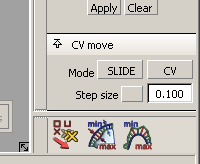
Orange and yellow arrows appear beside the selected CVs.
, click one of the yellow
arrows in the modeling window. Drag the mouse towards the left,
and notice the modifier surface becoming "flatter". Continue to
slide the CVs until the leftmost arrow touches the next CV to the
left, as shown here: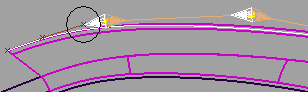
to reenter the tool (see
Part 2), double-click on the Transformer Rig icon in the toolbox
to open the option window, and click on Show All Geometry.
Optionally, turn off Draw Clamp Visualization under
the Visualization section. You
should then see something like this: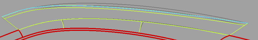
The green surfaces are the target surfaces post-modification. The cyan line is where the modifier is. The dark gray lines are the templated version of the original target surfaces. You can see how much you've flattened the surface.