Show in Contents

Add to Favorites

Home: Alias Help

Undo curve-on-surface

Modeling

Bezier option in Tube Surface

Symmetrical Modeling
Brand new functionality
lets you enter a symmetric modeling mode where
you can select geometry and modify it in a symmetric manner by moving
controls (CVs, edit points, and so on) on one side, and having the
corresponding controls on the symmetric half automatically move
in the opposite direction.
The symmetry plane is
defined by the default symmetry plane for the layer the curve or surface
belongs to. This plane can be modified by using Layers
> Symmetry > Set Plane. If you move the object,
the symmetry plane moves with it.
To modify a curve across
a centerline
- Create a curve across the Y axis.
- Choose Object Edit > Symmetric
Modeling.
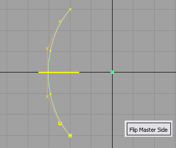
- Select the curve.
Symmetric constraint is applied to the curve.
If the curve is not symmetric, it is modified to be symmetric.
A yellow symmetry plane
is displayed. This plane corresponds to the default symmetry plane
for the layer the object belongs to (XZ plane by default). You can
modify it by using Layers > Symmetry > Set Plane.
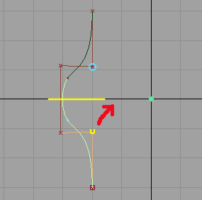
- Pick one or more CVs on one side of the
curve.
Blue
circles appear around the corresponding CVs on the symmetric half.
- Move the CVs (with Transform
> Move or the Move CV tool).
The selected CVs follow
the mouse. The symmetric CVs move in the negative direction on the
symmetric side of the plane.
The curve has construction history so that any
subsequent operation on the CVs will continue to maintain symmetry
across the plane. If you want to remove the symmetry constraint
from the geometry, delete the construction history.
If the whole curve is
moved, the symmetry plane moves with it but is drawn in a different
color to differentiate it from the layer symmetry plane.
Inputs and selection
- Regular curves and surfaces can be selected,
as well as Blend Curves. In the case of Blend Curves, only the position
of the blend points is supported by symmetric modeling (and not
other constraints such as tangent scaling). Blend curves where any
blend point is connected to geometry are not supported. Keypoint
curves can also be used, but will lose their keypoint attributes.
- Several curves and surfaces can be selected
at once.
- Geometry can be selected either before
or after entering the tool. Symmetry constraints are applied to
each curve or surface individually.
Modification
- CVs, edit points, and blend points can
be modified symmetrically.
- If the input curve or surface is not
symmetric, the tool modifies the controls of the model to ensure
that it is symmetric. The position of the controls from the beginning of
the curve or surface are applied to the symmetric partners at the
end of the curve or surface. Click the Flip Master Side button
to have it work the other way around.
- If a control (CV, edit point, or blend
point) is selected prior to entering the Symmetric Modeling tool,
the side of the object containing the picked control becomes the
master side and is not modified when the object is made symmetric.
- Any transformation tool can be applied
to the controls including Move, Rotate, Scale, Non
Proportional Scale, Move CV (XYZ,
Slide, NUV, Project) or Proportional Modification.
- Once the Symmetric Modeling tool
has been applied to a curve or surface, the controls will respond
to any transformation by also modifying their symmetric partner across
the plane of symmetry.
Symmetry plane
- The symmetry plane location and axis
direction is defined by the layer symmetry plane. By default this
plane is defined as Y=0 (XZ plane).
- The symmetry plane for each layer can
be modified individually by using the Layers > Symmetry
> Set Plane tool. Modification of the layer symmetry
plane does not affect the symmetry plane currently assigned to each
curve or surface.
- A symmetry plane is displayed for each
object selected.
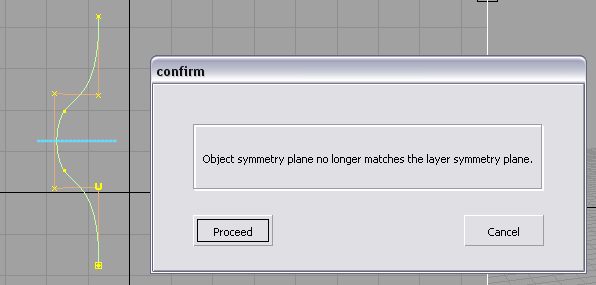
- Once defined, the symmetry plane is unique
to each curve or surface. When a curve or surface is transformed,
its symmetry plane becomes decoupled from the layer symmetry plane,
and follows the object. If the plane doesn’t match the layer symmetry
plane anymore, it is drawn in a different color. A confirm box also
appears in this case.
Undo
- If a curve or surface is modified while
establishing symmetric constraint, you can use Edit
> Undo (
 + Z) to return
it to its original state. Similarly, Undo works
with any symmetric modification to the controls, up to the limit
specified in General Preferences.
+ Z) to return
it to its original state. Similarly, Undo works
with any symmetric modification to the controls, up to the limit
specified in General Preferences.
- You can return a curve or surface to
its normal state (without symmetric constraint), while maintaining
the modifications to the controls, by removing the construction
history with Delete > Delete Construction History,
or by using the History View window (Windows
> Information > History View).