To create stereo, run-length-encoded images for display on the Stereographics monitor, several changes must be made to an ordinary SDL file.
DEFINITION Section Changes for stereo pairs
First, a flag must be set in the DEFINITION section to have the renderer create a stereo pair. The syntax for it is:
stereo = <scalar>;
where the value of the scalar is 0 (FALSE) or not 0 (TRUE).
The setting of these variables can be performed in the interactive package through the camera editor.
The stereo flag specifies if the camera(s) is to render a stereo pair of images. If this component is TRUE, the pix and mask components (if specified) will have two file names generated for the left and right images.
The generated names will be,
"<specified_name>_left"
"<specified_name>_right"
The “left” and “right” correspond to the output pix files for the left and right eyes. The filename may be animated like other animated filenames (that is, “basename”extension_expression). If the extension expression is missing and the rendering is an animation, the name will have a standard frame extension. Any extension is appended after the suffixes "_left" and "_right".
For example, if the SDL contained camera (pix="pix/abc",... and it were animated, the renderer would create two pix files for the first frame,
"pix/abc_left.1" and "pix/abc_right.1"
One other variable must be set:
stereo_eye_offset = <scalar>;
The offset specifies the eye separation between the eye points of two cameras that will be used to render the stereo pair. The offset is in world coordinates and specifies the eye’s off-set in X. This variable can also be set in the camera editor in the interactive package.
Example:
stereo_eye_offset = 0.55;
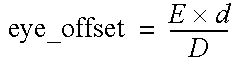
The parameter stereo_eye_offset specifies the spacing between the eyes in modeling space. A single value, it controls the amount of disparity between the two eyes by offsetting the eye point for each image by the amount specified. The value of stereo_eye_offset can be computed to a first approximation as follows:
If D is the distance in inches that the person sits from the screen, for example, 19 inches, and E is half the distance between the left and right eye (for example, E = 1.5 inches), then

Note the camera view position in the interactive package. It is used to determine the zero parallax depth for the scene. The view position is the point at which the left and right images will be coincident on the screen. It should be chosen close to the centre of attention.
In addition to the "stereo" switch and the "stereo_eye_offset", other changes must also be made.
Set the resolution for stereo images to 1280 by 480, if you are using the Stereographics monitor.
Good quality is necessary for stereo images. Ensure that the aalevel (both min and max) and aathreshold values are set appropriately.
The viewport for stereographic viewing should always be 0 1279 0 479. For the aspect, use 1280/1024 (the value will be computed).
The fov should be adjusted to the viewing distance between the user and the stereographic screen. In the attached example, set for a viewing distance of 19 inches, the fov = 2.0*atand(4.5/19.0).
If any lights of type ambient are used, ensure that the ambient_shade value is set to 0 (it defaults to 0.5) for each. If it is set to a value other than 0, the lighting will be different for each eye.
Render this SDL file once to create the pix files for both eyes.
To view these files on the Stereographics monitor, use the stand alone program showstereo. If the pix files are not full screen resolution (1280 by 480), they will be resized to the correct resolution automatically, by pixel replication if they are too small, or by truncation if too large. If the image is too large, as much of the image as can fit on the screen will be shown, from the upper left corner.
Alternatively, you can use the standalone utility rb_stereo to create a red-blue stereo image that can be viewed on the monitor with readily-available red-blue “stereo” glasses.
Helpful Hints for Stereo Image Modeling
When creating images for stereo pairs, some effects work better than others. Keep the following in mind when creating your model:
A useful example file is found in CourseWare/SDL/stereo.


