Building primary and transition
surfaces using the fillet flange and tube flange tool
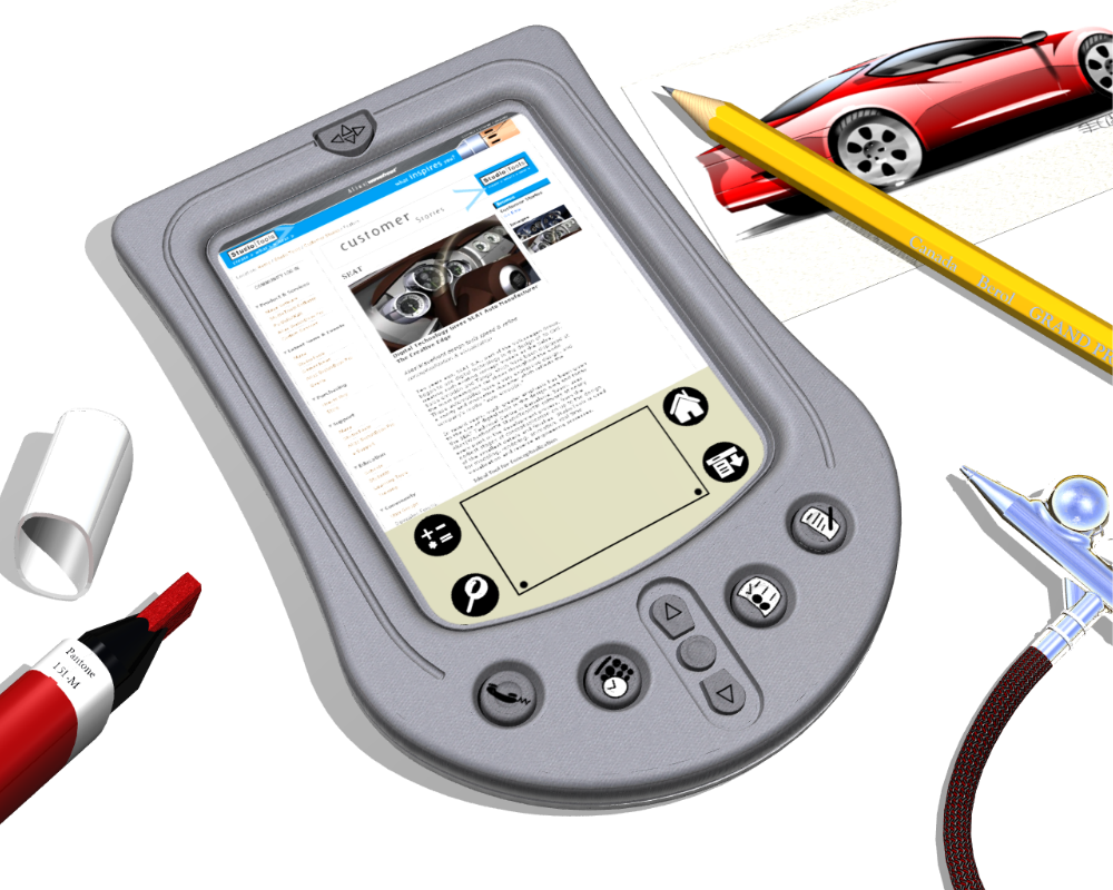
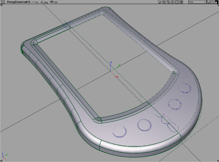
How to build a PDA using Fillet Flange and Tube Flange.
 ❒, then click the trimmed edge of the top
surface.
❒, then click the trimmed edge of the top
surface.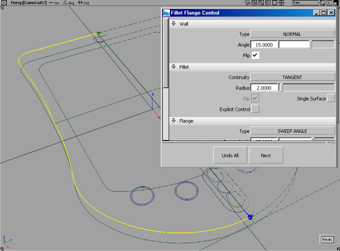
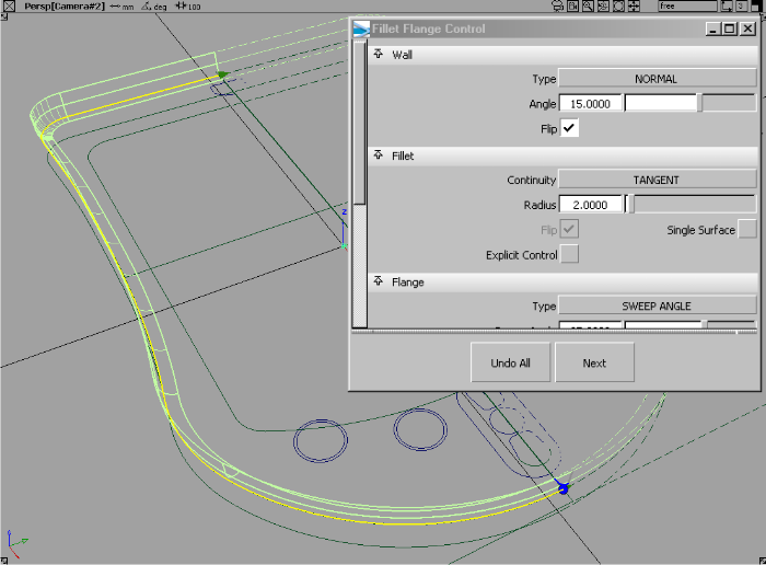
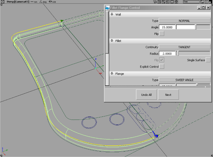
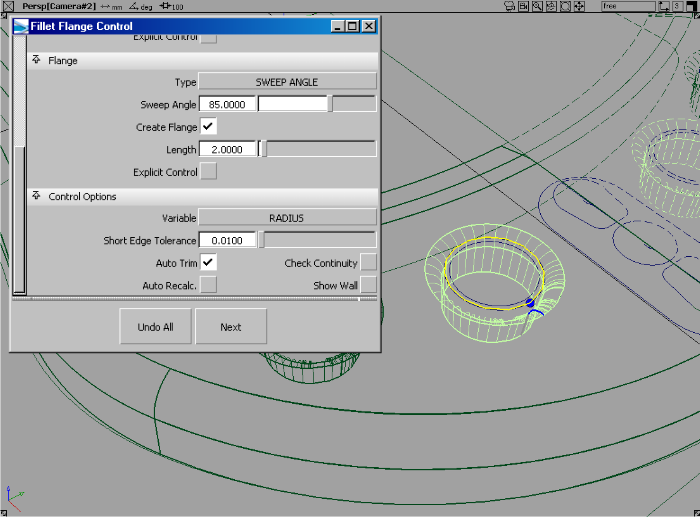
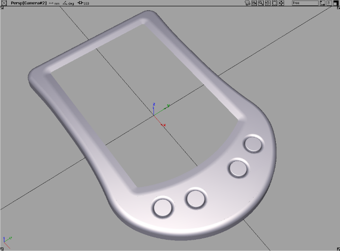
In this example we have set a 15 degree taper on the wall and a two unit fillet. You should notice immediately this tool first builds a flange wall, and then fillets between the flange wall and the input surface in one very simple workflow.
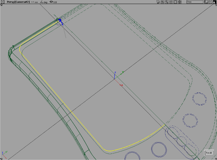
 to evaluate the surfaces.
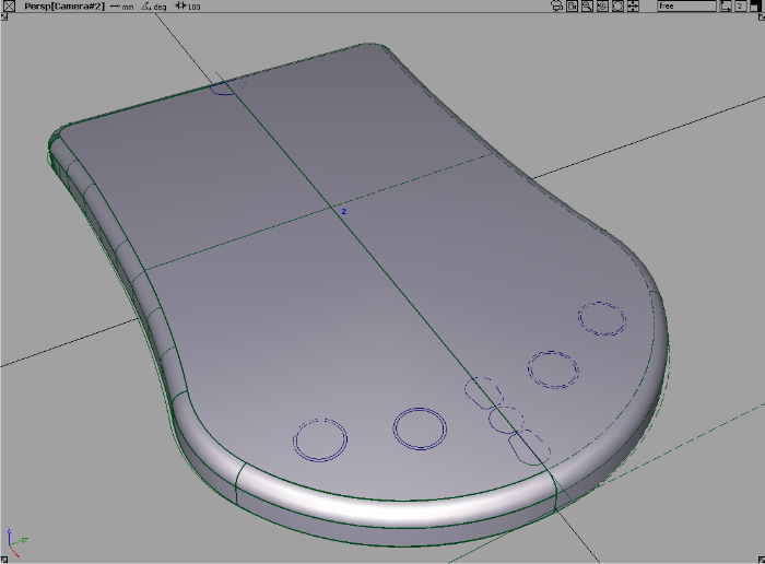
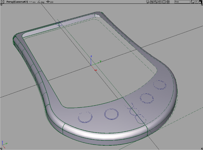
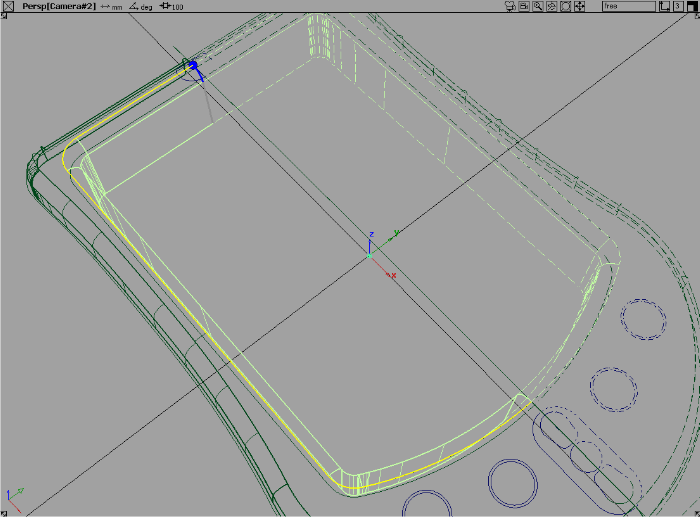
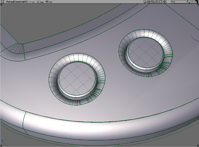
 to create a blended inner
surface for the LED area.
to create a blended inner
surface for the LED area.
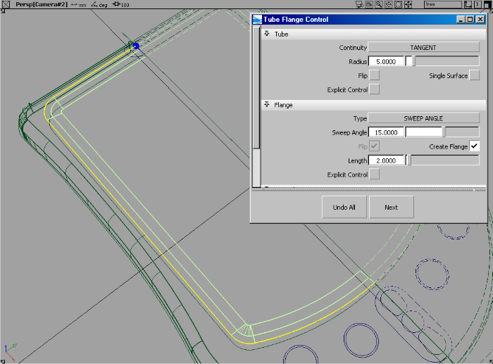
By default, the tube is 1 unit and the flange is built at 90 degrees.
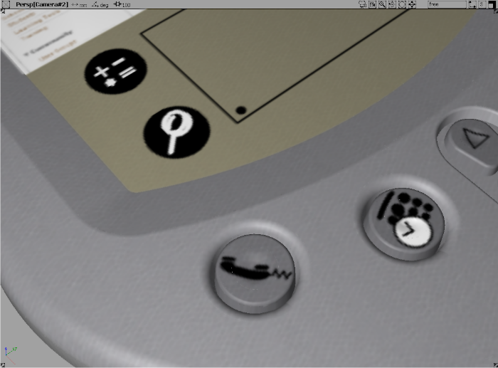
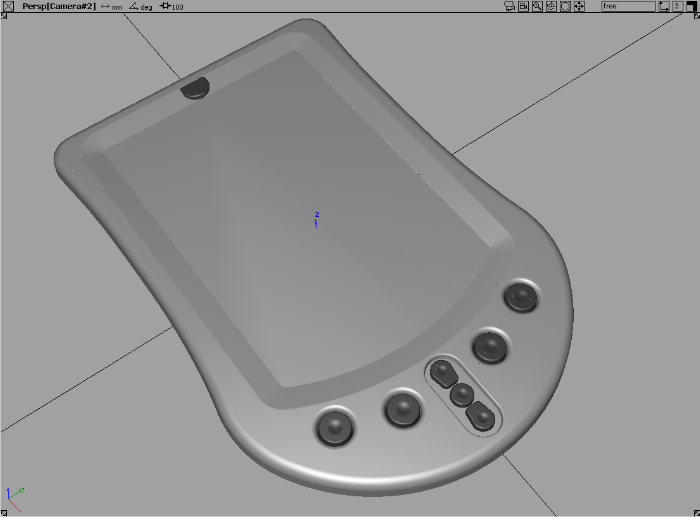
Building button holes and buttons
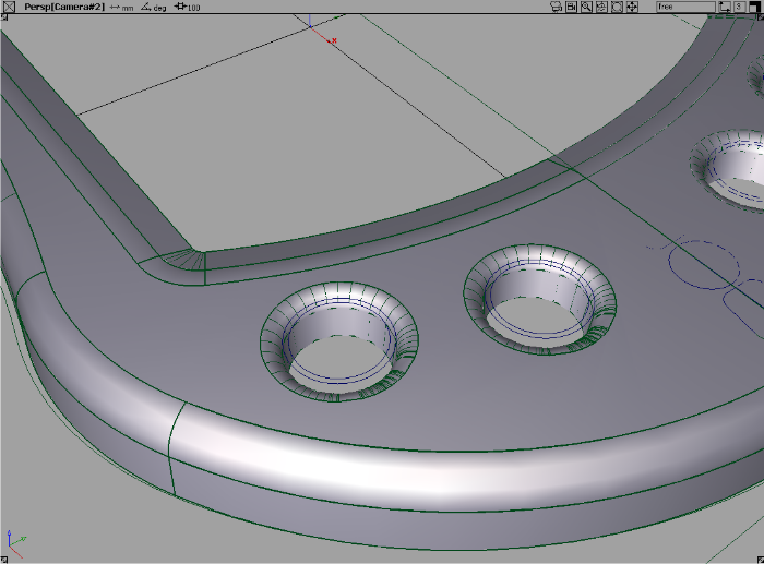
to create the blend recesses
for the buttons.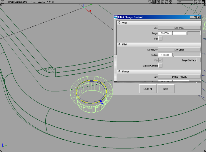
 to create the tops of the
buttons using simple circle curves.
to create the tops of the
buttons using simple circle curves.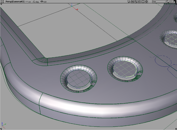
to create the filleted flange
surfaces that are needed for the button edges.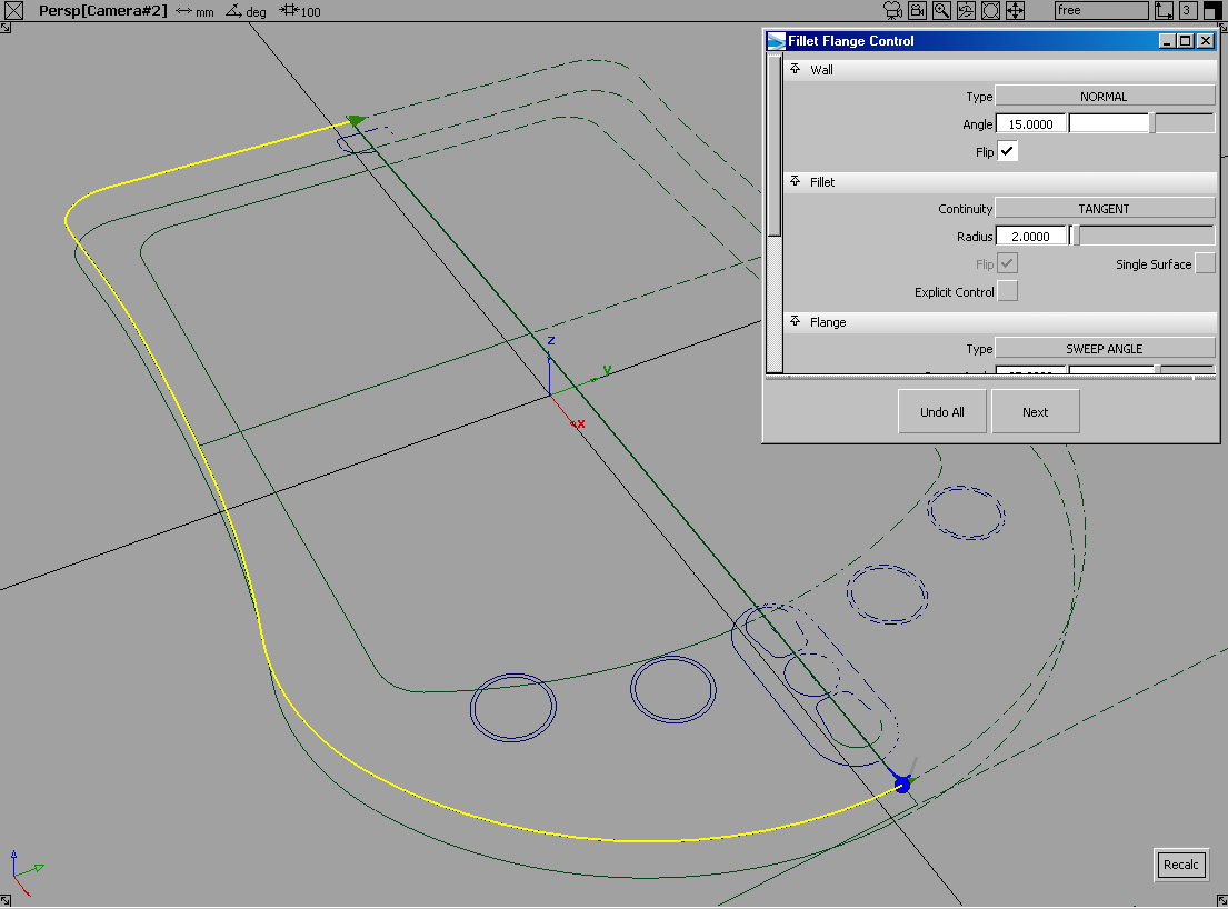
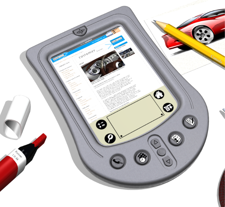
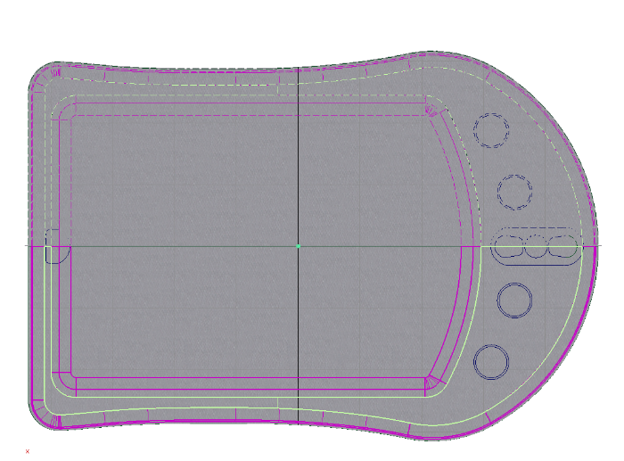
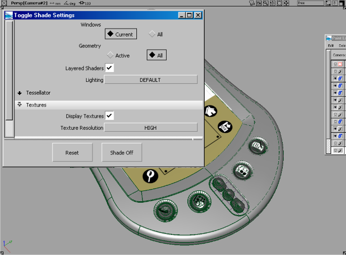
Next, we’ll add some graphic design detail to our concept model. In this example we have turned off the gray plastic paint layer and selected all the surfaces highlighted in red.
 options window, select Active
View and Active Objects, then click Go.
options window, select Active
View and Active Objects, then click Go.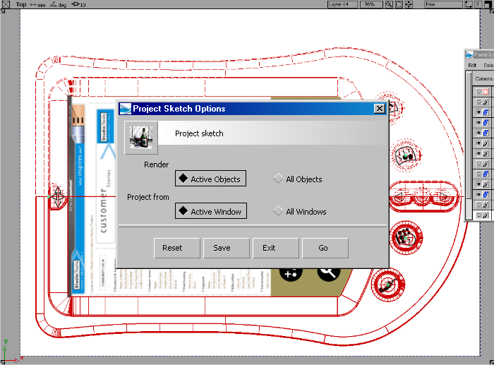
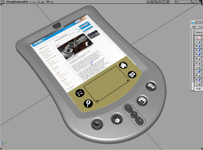
Originally, we created the quick concept sketch using a texture brush to create a plastic finish for the PDA.
 ) and turn this
layer back on.
) and turn this
layer back on.
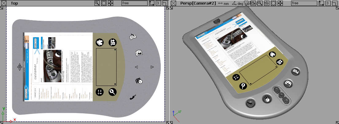
Here is a close-up to show the faint plastic finish painted on the 2D image layer.