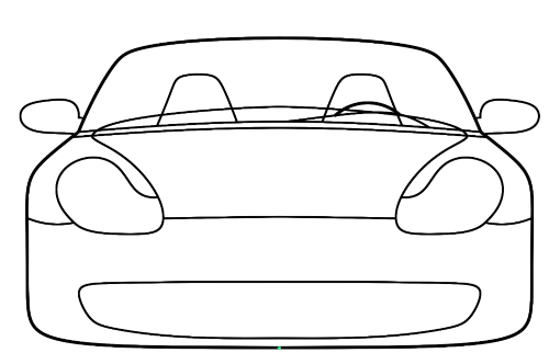
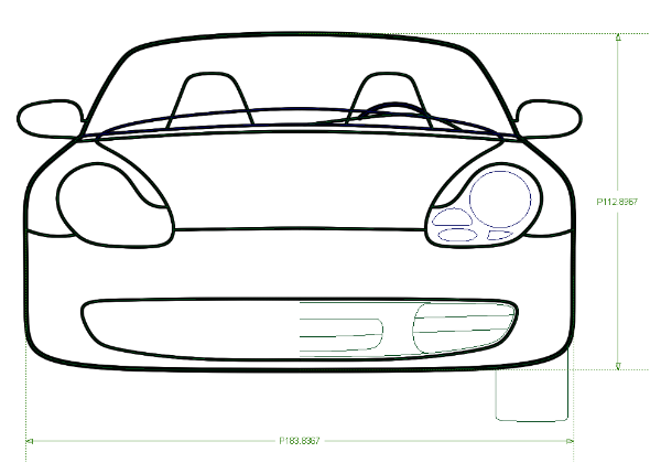
Create accurate digital tape drawings easily within Alias by using the automatic shape creation option as curves are created. This How-To provides the basic workflow for creating a front view tape drawing.
 or
or  + 3 (Windows)
or
+ 3 (Windows)
or  + 3 (Mac)
to ensure Alias is displaying all the 3D menus.
+ 3 (Mac)
to ensure Alias is displaying all the 3D menus.
 to set your working units.
In this example, we set the Main Units to cm and
turn on Reset Grids.
to set your working units.
In this example, we set the Main Units to cm and
turn on Reset Grids.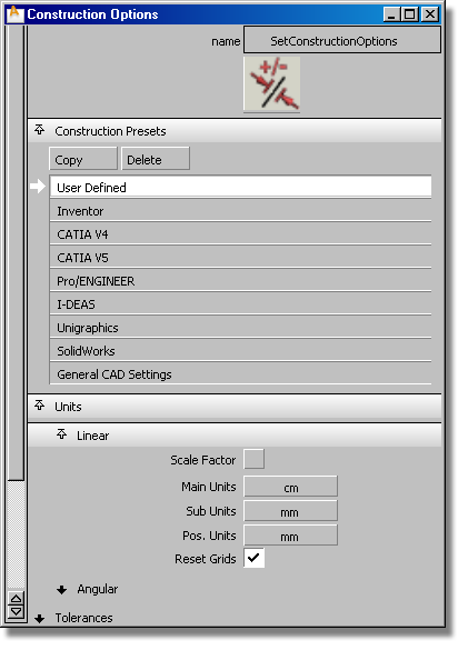
 from the tool palette. Turn
on Labels if you want to see grid
labels. Make sure Grid Spacing is set to 10.0 so
grids are drawn every 10 cm.
from the tool palette. Turn
on Labels if you want to see grid
labels. Make sure Grid Spacing is set to 10.0 so
grids are drawn every 10 cm.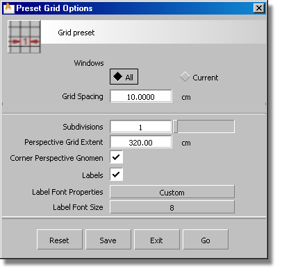
 to create a working geometry
layer. Make it active by clicking on it (the button will be drawn
in yellow).
to create a working geometry
layer. Make it active by clicking on it (the button will be drawn
in yellow).
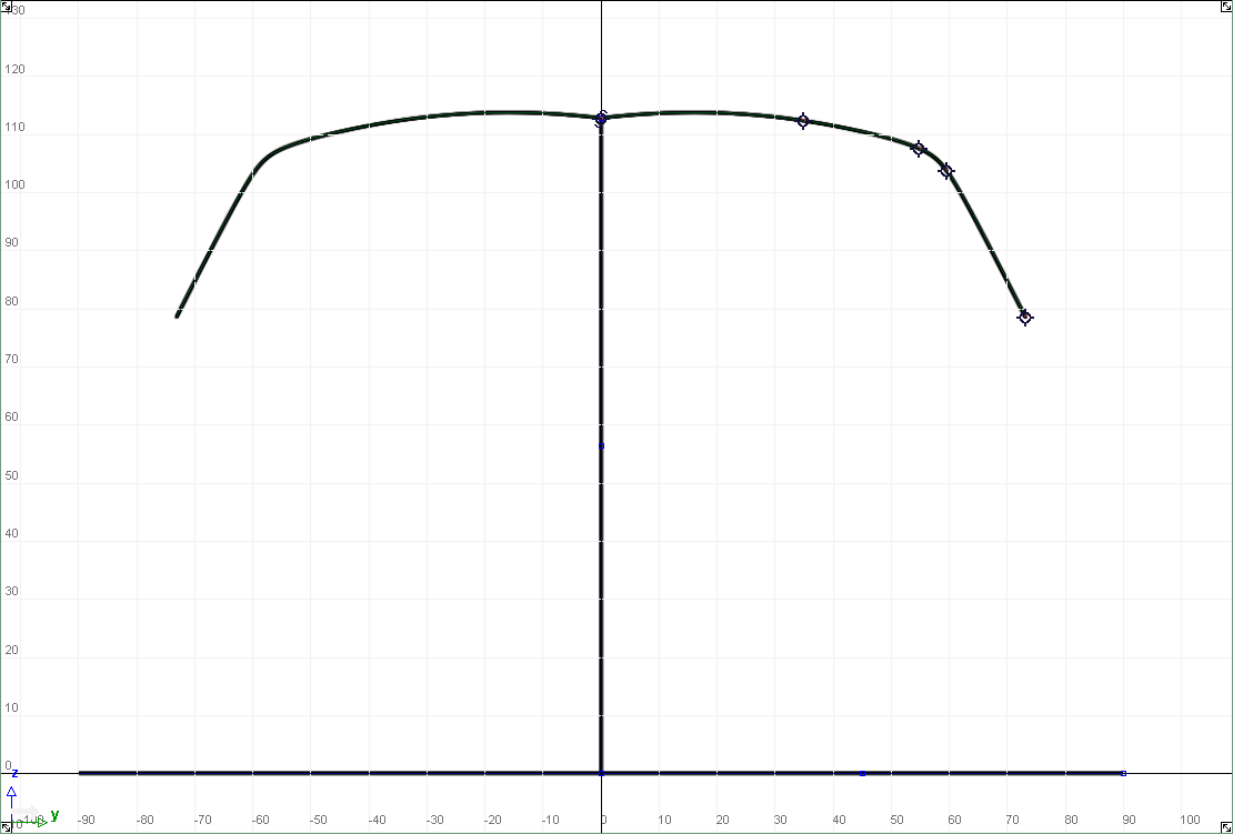
We want the front view of the car to be symmetric across the center line (Z axis). Layer symmetry will automatically reflect the curves and create shape objects as we draw curves. This means this geometry layer will now automatically create curves across the Z axis.
Using Automatic shape creation options
 to turn on 2D paint menus.
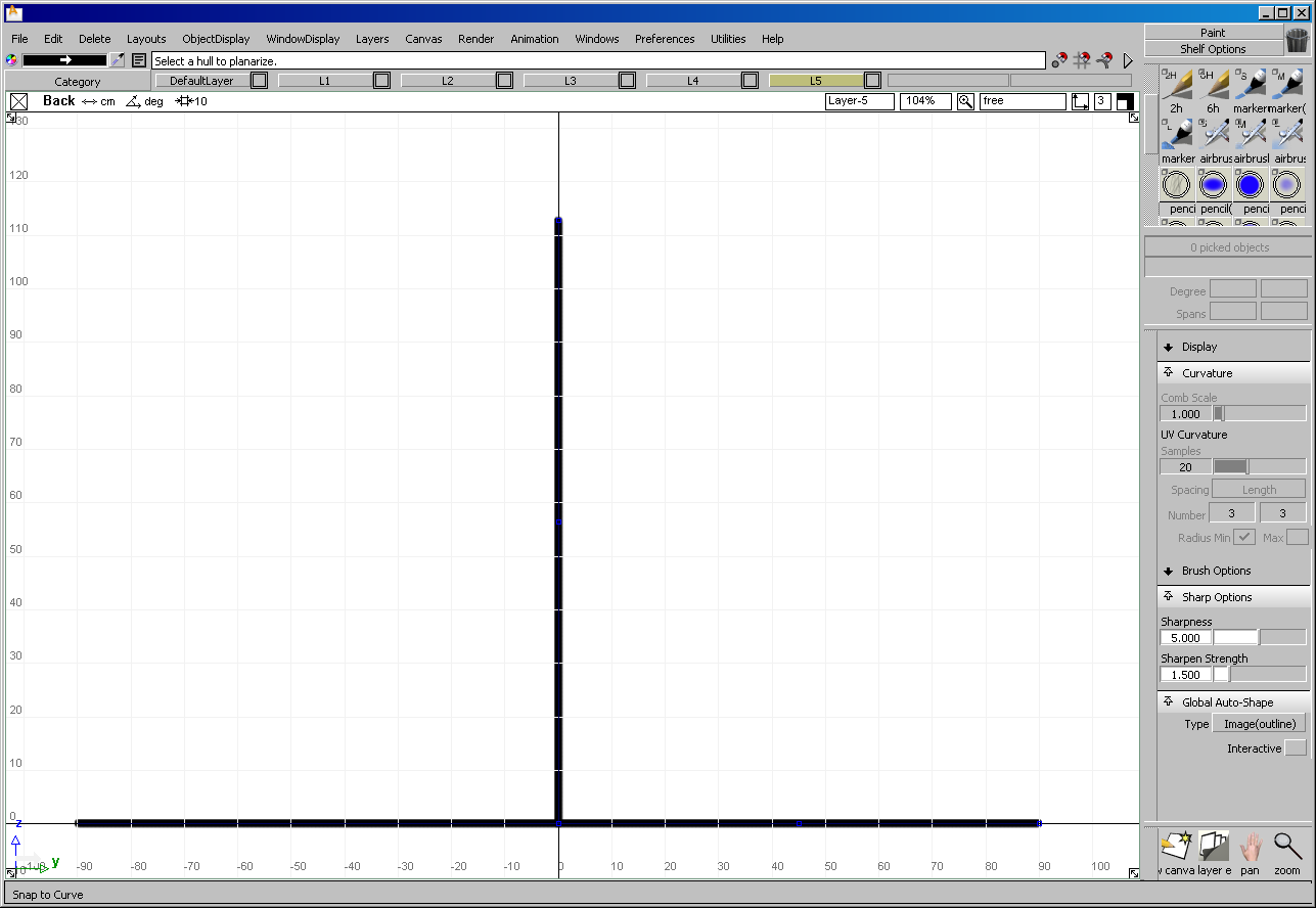
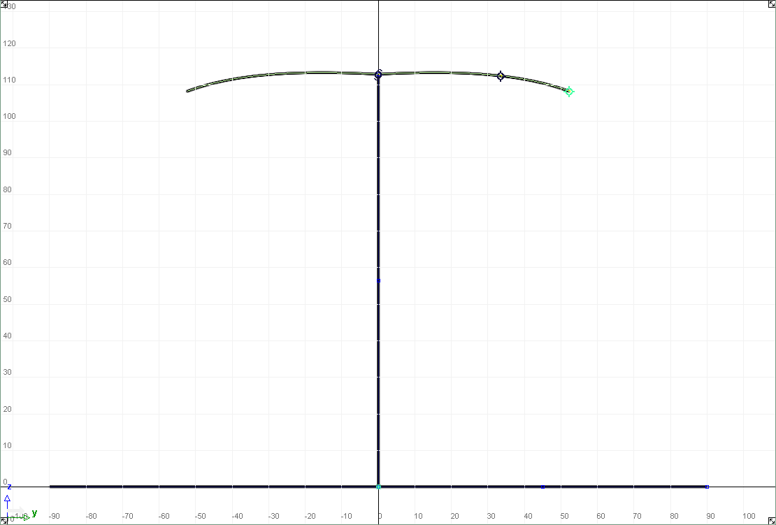
 tool. Place the first point
at 0,0,0 and the second point at 0, 90 cm, 0. Notice how the shape
is automatically drawn on the left side of the construction plane.
Using the object information window you can adjust the line length
to accurately define half the width of the car.
tool. Place the first point
at 0,0,0 and the second point at 0, 90 cm, 0. Notice how the shape
is automatically drawn on the left side of the construction plane.
Using the object information window you can adjust the line length
to accurately define half the width of the car.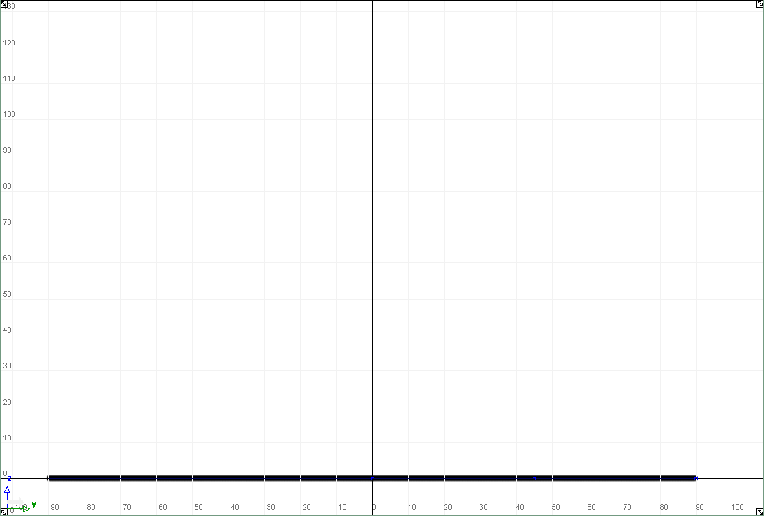

 .
.
Changing Canvas Plane Resolution
 ❒ to open the Resize Canvas Control window.
Adjust the canvas Width to 2000 pixels and the Height to
1800 pixels.
❒ to open the Resize Canvas Control window.
Adjust the canvas Width to 2000 pixels and the Height to
1800 pixels.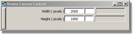
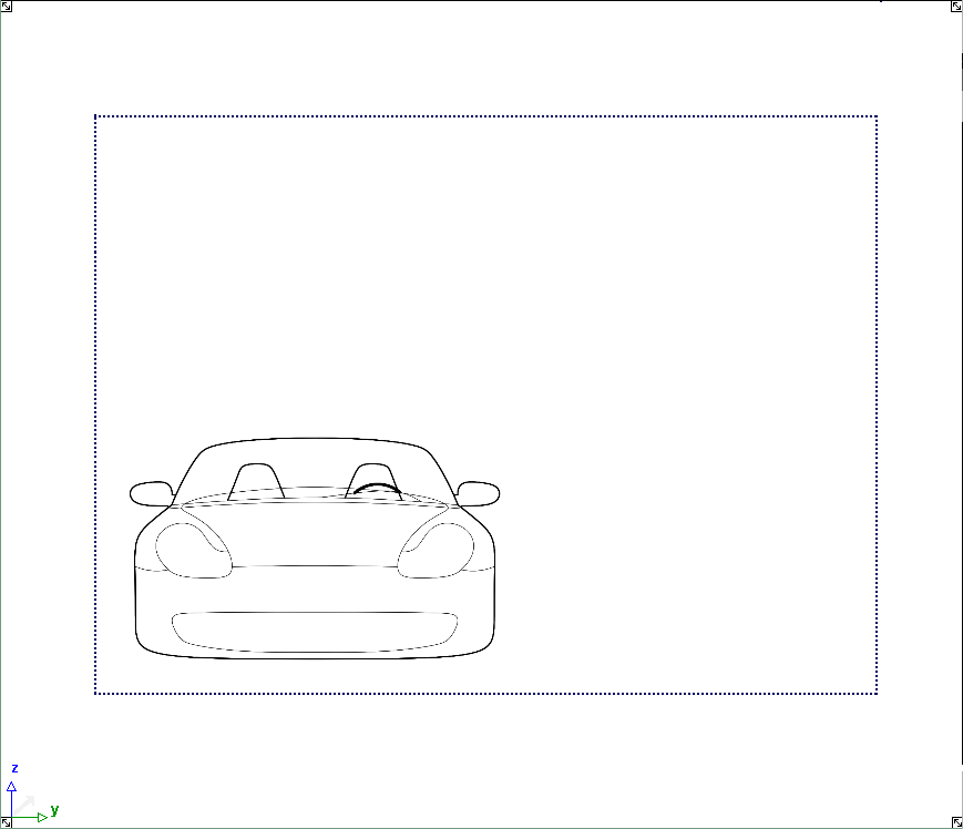
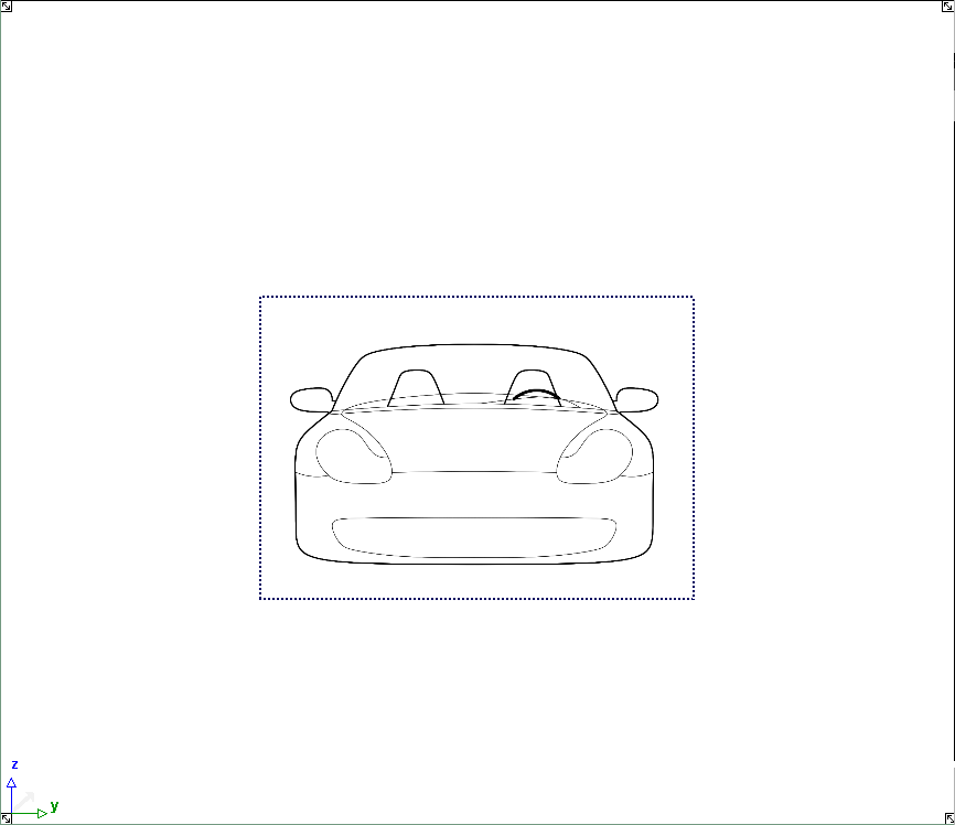
and drag the corner selection
handle to increase the size of the canvas plane to be large enough
to encompass all curves. Notice that the shapes automatically re-render
to a new image resolution every time the canvas plane is transformed.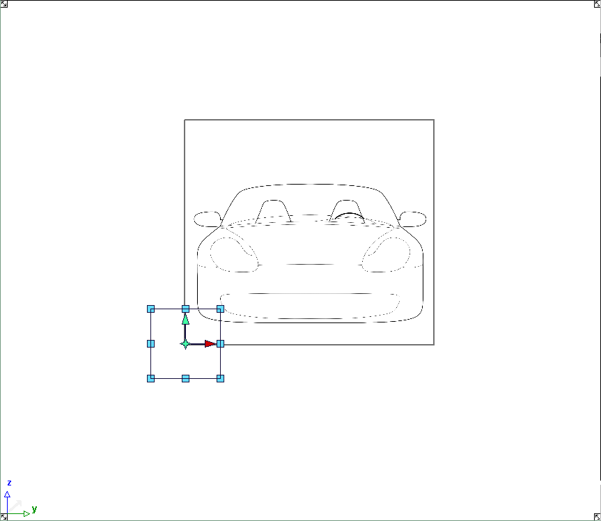
 (rectangle) and
select the area of the canvas plane to keep.
(rectangle) and
select the area of the canvas plane to keep.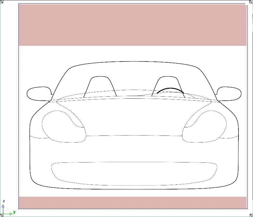
 to reduce the canvas plane
size. Note the marquee tool and crop can also be used to make a
canvas plane larger.
to reduce the canvas plane
size. Note the marquee tool and crop can also be used to make a
canvas plane larger.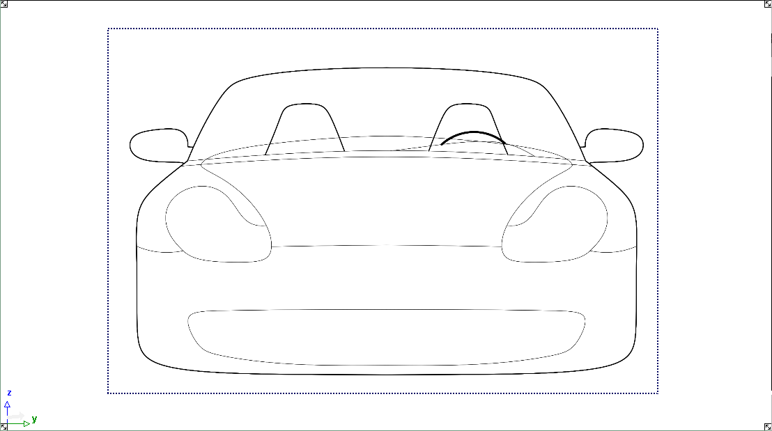
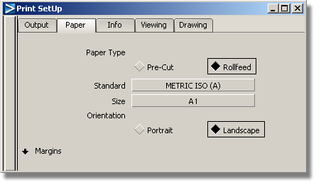
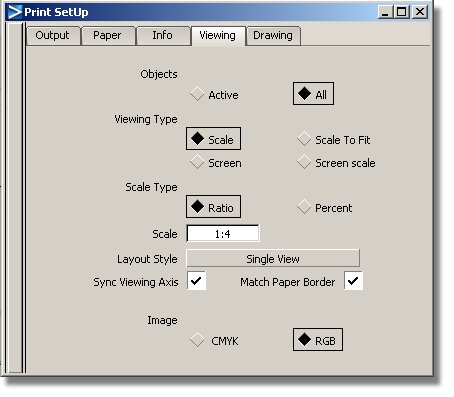
Lets assume you now want to print your tape drawing at ¼ scale. A number of options need to be set before your can make a successful print.
 and on the Output tab,
choose a printer; in this example, we will print on a large format
roll feed printer using the output postscript print language.
and on the Output tab,
choose a printer; in this example, we will print on a large format
roll feed printer using the output postscript print language.
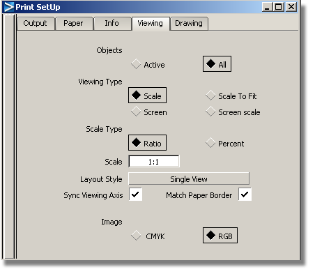
Note the active window is used by default to create a single view layout.
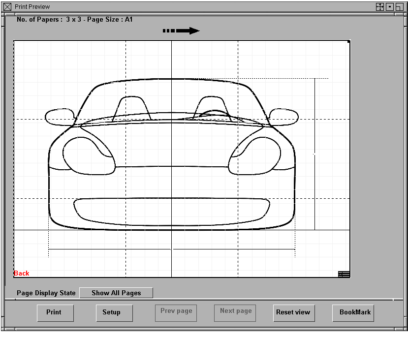
The print preview window shows dotted line pages. At a scale of 1:1, this image requires 9 pages of A0 size paper.
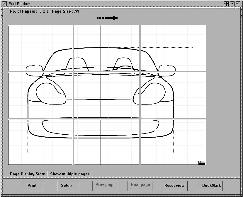
 +
+  +
+  (Windows) or
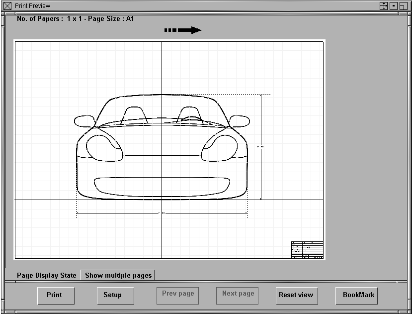
  + + (Mac)) in the preview window
to adjust exactly how the image will be positioned on the paper.
+ + (Mac)) in the preview window
to adjust exactly how the image will be positioned on the paper.
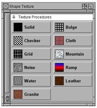
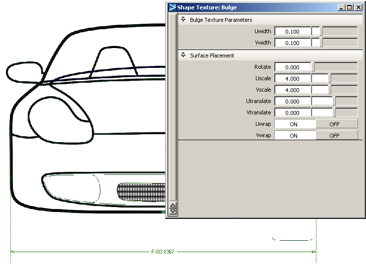
Adding Simple Texture To a Tape Drawing
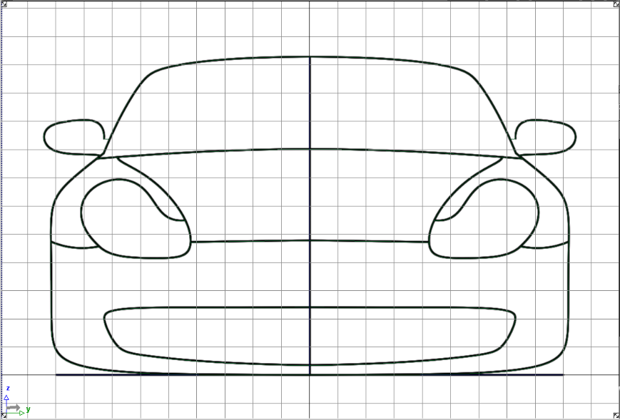
When creating a tape drawing, designers often add solid color and texture to improve the appearance of the image. In this example we will use the Make Shape tool to add this detail.
At the moment the additional curve detailing is assigned to the default 3D geometry layer, so we need to create new symmetry layers and assign the geometry to them.
 to make all modeling tools
available.
to create a new geometry
layer. A geometry layer will be added to the horizontal bar. Double
click the new layer and type a name, for example, Headlights.
to make all modeling tools
available.
to create a new geometry
layer. A geometry layer will be added to the horizontal bar. Double
click the new layer and type a name, for example, Headlights.
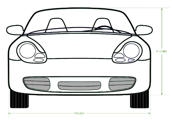
 select the curves that define
the grill detailing and assign them to the Grill layer using the
Grill layer drop-down menu.
select the curves that define
the grill detailing and assign them to the Grill layer using the
Grill layer drop-down menu.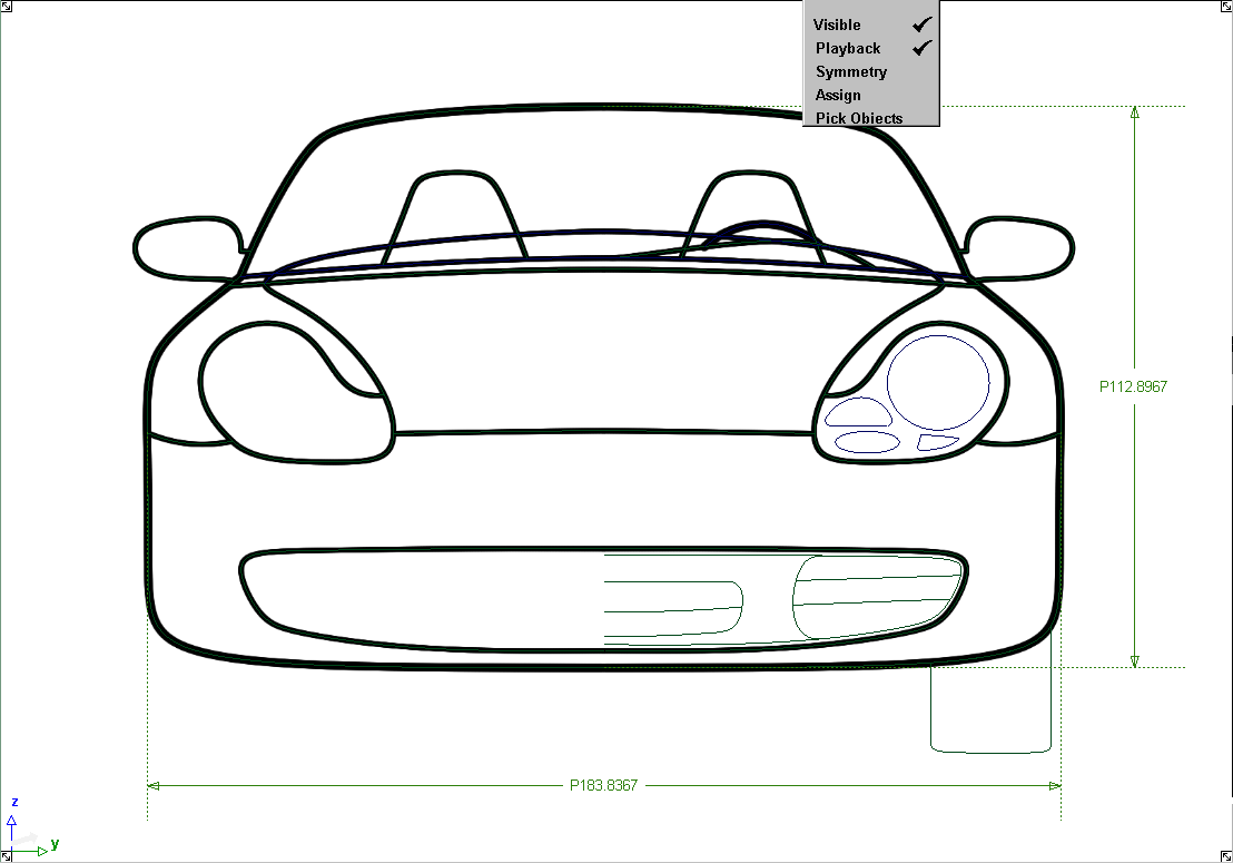
 and select the curves that
define the center grill. Note you need only select one half of the
grill curves.
and select the curves that
define the center grill. Note you need only select one half of the
grill curves. 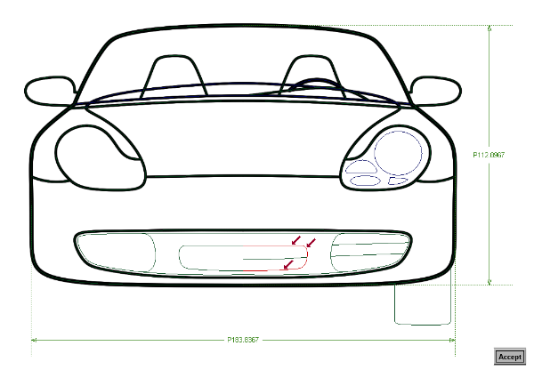
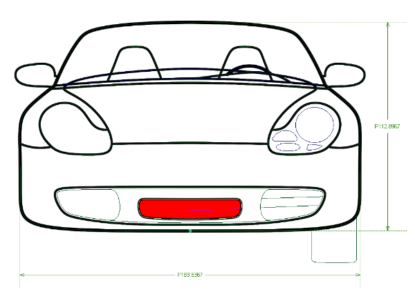
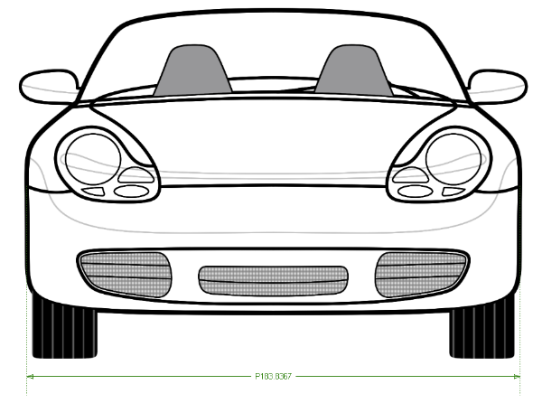
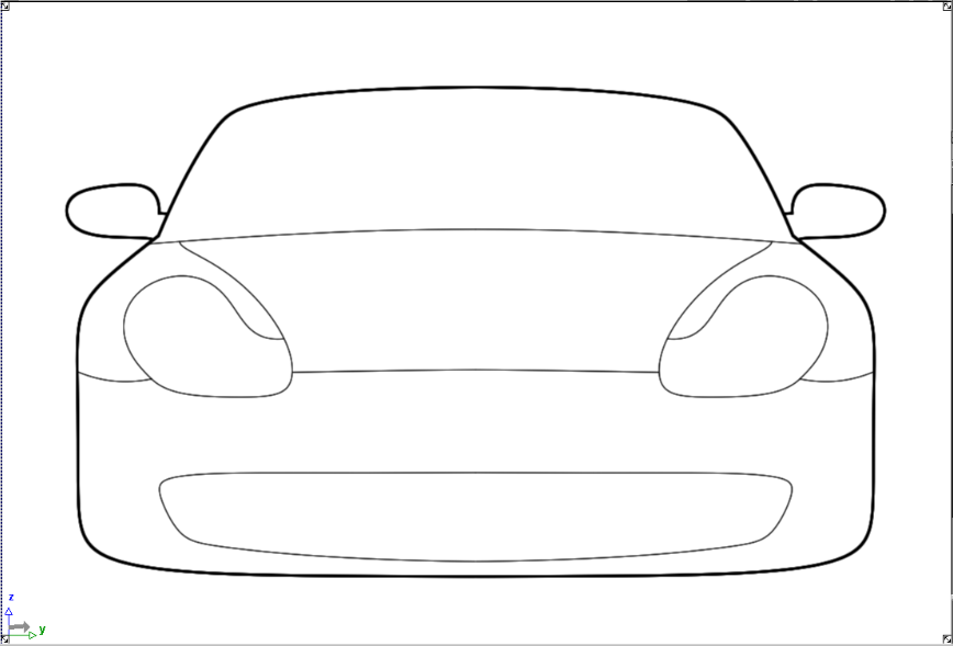
Congratulations! You’ve now completed a tape drawing using Alias.


