Cubic environment maps provide a fast and attractive way to simulate a one-bounce ray trace. The object to which a cubic environment (sometimes called a cubic reflection) map is applied, appears to reflect its environment. This tutorial will demonstrate a method for creating cubic environment maps for two types of reflections. The first will show how to create the reflection map for a non-planar object in the scene, and the second will show how to create a reflection map for a reflective plane (that is, a floor or a wall).
The basic steps involved in creating the reflection map files are as follows:
Reflection Map for a Non-planar Object in the Scene
A cubic environment map requires six pix files that show what is seen along each of the positive and negative axes directions from a spiced point. It is the specification of the point that allows us to create the reflection map for certain types of reflections.
Let us assume that we want to render a cubic reflection map for a sphere that is inside a room:
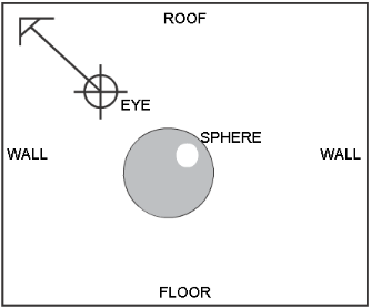
Sphere to be reflection mapped
In order to create a reflection map of what is seen from the sphere, we must create a special SDL file. This file will have an eye point positioned at the centre of the sphere (or at the center of whatever object we want). This file will NOT contain the sphere, however. This is because if the sphere were in the SDL file, when we render from the centre of the sphere all we will see is the inside of the sphere and not what is around the sphere (its environment). It is important to always remove the object that we are creating the environment map for from this special SDL file.
Once the eye point is placed at the centre of the object, and that object is removed from this special SDL file, we must insert the animation statements for the eye direction.
Let us assume that the centre of our sphere (and thus, our eye) is at (0, 0, 0). The first thing we do is remove the “view” statement from the MODEL section and replace it with a new camera. It is very important to change the field’s fov to 90.0, twist to 0.0, and aspect to 1.0. Our camera section now looks like:
camera (eye = (0, 0, 0),
view = camera_view,
fov = 90,
viewport = (0.0, 255.0, 0.0, 255.0),
aspect = (1.0)
);
In order to use this camera, it must be defined in the DEFINITION section:
triple camera_view (0.0, 0.0, 0.0);
In order to create the pix files from this little animation, the DEFINITION section must include:
startframe = 1;
endframe = 6;
It is also important to remember that we are creating pix files that are to be used as texture maps, so the resolution should be one of 256, 512, 1024, and so on.
The final step is to add animation to the MODEL section, also as described in this manual:
if ( frame == 1.0 ) camera_view = (1.0, 0.0, 0.0);
else if (frame == 2.0 ) camera_view = (-1.0, 0.0, 0.0);
else if (frame == 3.0 ) camera_view = (0.0, 1.0, 0.0);
else if (frame == 4.0 ) camera_view = (0.0, -1.0, 0.0);
else if (frame == 5.0 ) camera_view = (0.0, 0.0, -1.0);
else if (frame == 6.0 ) camera_view = (0.0, 0.0, 1.0);
After rendering this special SDL file, we return to the original SDL file and add the reflection map to the shader that corresponds to the object (in this case, a sphere).
shader AAA ( model = phong,
diffuse = 0.800000,
shinyness = 10.000000,
color = (0.0, 0.0, 0.0),
specular = (0.800000, 0.800000, 0.800000),
reflectivity = 1.0,
reflection = texture(procedure = Cube,
right = "pix/special.1",
left = "pix/special.2",
top = "pix/special.3",
bottom = "pix/special.4",
front = "pix/special.6",
back = "pix/special.5"
)
);
The sphere will now have a reflection of the environment on it.
Reflection Map for a Reflective Plane
The first section described how to create and use a reflection map for an object in the scene. Creating reflection maps for planar objects (say a shiny floor) is done in a different manner.
Creating a reflection map for a planar object is easiest if the planar object lies on one of the XY, YZ, or XZ planes. If this is not the case, then calculation of the eye point for the special SDL file is difficult, but it can still be done.
Let’s start with the simplest case. We have a planar object that lies on the XZ plane (see below). For simplicity, we will refer to this planar object as the floor of our modeled room, in a Y-up environment.
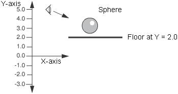
Reflection map for planar object
What we will do, in effect, is mirror our eye point in the floor. The equation to do this mirroring for the example above is:
eye_Y' = floor_y – (eye_y – floor_y) (1)
Substituting in our values from the example and solving:
eye_Y' = 2.0 – (5.0 – 2.0)
eye_Y' = 2.0 – (3.0)
eye_Y' = –1.0
So, in our special SDL file, we change only the eye’s Y value to be this new Y' value. We then replace the “view” statement with a new view statement as with the first example. For example, if the CAMERA section was
Camera (
eye = (3.0, 5.0, –2.0),
view = (0.3, 1.2, 9.3),
fov = 40.0,
aspect = 1.316
);
then we would change it to
camera (
eye = (3.0, -1.0, –2.0),
view = camera_view,
fov = 90,
viewport = (0.0, 255.0, 0.0, 255.0),
aspect = (1.0)
);
and, as before, we would change the output pixel resolution to one of 256, 512, 1024, 2048, and so on, and add the animation to the MODEL section for x_dir, y_dir, and z_dir. This special SDL file is rendered and the reflection map is applied to the floor’s surface descriptor in the original SDL file. Remember to remove the floor in the special SDL.
If the planar object is not on the XZ plane, then the modified coordinate can be found by substitution of X for Y in equation (1) if the object lies in the YZ plane or by substituting Z for Y in equation (1) if the object lies in the XY plane.
If the planar object does not lie in one of the above planes, then it becomes more difficult to calculate the new eye point, and it requires a lot more math.
Let’s say that our planar object is described as a face that has the following points in the SDL file:
X Y Z
V1 –0.4183 –4.64 2.5132
V2 –3.905 –1.084 2.5716
V3 0.114 3.2474 –1.6657
V4 4.1738 –0.3513 –2.0018
And assume that the eye is at (0.5, 0.5, 12).
Now, in order to reflect the eye point in this plane, we will need a normal to this plane. To calculate the normal, we need 3 of the vertices of the planar object. Let us arbitrarily choose V1, V2 and V3, which from inspection of the wire frame, we know do not lie in a straight line (in mathematical terms, the points are not co-linear).
DX2 = V2.X – V1.X (2)
DX3 = V3.X – V1.X (3)
DY2 = V2.Y – V1.Y (4)
DY3 = V3.Y – V1.Y (5)
DZ2 = V2.Z – V1.Z (6)
DZ3 = V3.Z – V1.Z (7)
The results of equations (2) through (7) are then used to compute:
L = DY2 *DZ3 – DY3 * DZ2 (8)
M = DX3 * DZ2 – DX2 * DZ3 (9)
N = DX2 * DY3 – DX3 * DY2 (10)
R = L * L + M * M + N * N (11)
R = SQRT(R) (12)
L = L/R (13)
M = M/R (14)
N = N/R (15)
P = L * V1.X + M * V1.Y + N * V1.Z (16)
Now, you might think that all of that is far too much math for one day, but we’re not done yet. (SQRT(R) in equation (12) means that we want the square root of the number represented by R.)
The distance of the eye point from this plane is calculated by:
D = L * EYE_X + M * EYE_Y + N * EYE_Z + P (17)
If D is negative, then the new eye point is given by:
D = 2 * (–D)
EYE_X' = EYE_X + D * L (18)
EYE_Y' = EYE_Y + D * M
EYE_Z' = EYE_Z + D * N
If D is positive, then the new eye point is given by:
D = 2 * D
EYE_X' = EYE_X + D * (–L) (19)
EYE_Y' = EYE_Y + D * (–M)
EYE_Z' = EYE_Z + D * (–N)
If D turns out to be equal to 0.0, then the eye point is on the plane and you should not create a reflection map for this object, because a mirror viewed “side on” does not reflect anything.
Returning to our example and placing the values into equations (2) through (7) we get:
DX2 = –3.905 – –0.4183 = -3.4867
DX3 = 0.114 – –0.4183 = 0.5323
DY2 = –1.084 – –4.64 = 3.556
DY3 = 3.2474 – –4.64 = 7.8874
DZ2 = 2.5716 – 2.5132 = 0.584
DZ3 = –1.6657 – 2.5132 = –4.1789
Placing these values into equations (8) through (10) we get:
L = 3.556 * –4.1789 – 7.8874 * 0.584 = -19.46641
M = 0.5323 * 0.584 – –3.4867 * –4.1789 = –14.2597
N = –3.4867 * 7.8874 – 0.5323 * 3.556 = –29.39385
Using these values in equations (11) and (12) we get:
R = –19.46641 * –19.46641 + –14.2597 * –14.2597 + –29.39385 * –29.39385
= 1446.27858
R = SQRT (1446.27858) = 38.02997
Then applying equations (13) to (15) we get:
L = –19.46641/38.02997 = –0.51187
M = –14.2597/38.02997 = –0.37496
N = –29.39385/38.02997 = –0.77291
Then we take a break to catch our breath and continue by applying equation (16) to these numbers:
P = –0.51187 * –0.4183 + –0.37496 * –4.64 + –0.77291 * 2.5132 = 0.011452
After applying equation (17) we get:
D = –0.51187 * 0.5 + –0.37496 * 0.5 + –0.77291 * 12.0 + 0.011452 = –9.70688
We can see that D is negative, so we apply equation (18):
D = 2 * (– –9.70688) = 2 * 9.70688 = 19.41376
Note that the negative of a negative number is a positive number, and continue with equation (18):
EYE_X' = 0.5 + 19.41376 * –0.51187 = –9.43732
EYE_Y' = 0.5 + 19.41376 * –0.37496 = –6.77938
EYE_Z' = 12.0 + 19.41376 * –0.77291 = –3.0051
Now that we have our new eye point, we go back to our special SDL file, and replace all three eye components:
eye = (–9.43732, –6.77938, –3.0051),
And again, as before, we replace the rest of the camera data, set the proper resolution, add the animation to the MODEL section and render this special SDL file to create the reflection map.
Shadows do not show up on surfaces that get all of their color from a reflection map. In order for a shadow to appear on a reflection-mapped surface, the surface must have a non-zero diffuse value.
A reflection-mapped object does not reflect itself. For example, a teapot will not reflect its spout, but it will reflect the rest of the scene. This is because we have to remove the object which will reflect from the special SDL file we create. To get proper reflections of an object with itself requires ray tracing. This method provides a cheaper alternative to ray tracing.
The methods for creating reflection maps described in this tutorial are for a static object in the “reflection maps for an object” case and for a static object and eye in the “reflection maps for planar surfaces” case. Should you wish to create high quality reflections for a moving object in an animation, then a new reflection map will have to be created for each frame of the animation. In the case of planar objects, some time can be saved by noting that some of the reflection map views do not “see” anything and are therefore black. These views only need to be created once for the entire animation.


