Creates cross section geometry on selected surfaces or meshes.
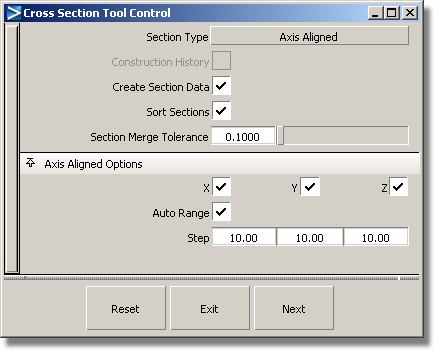
Axis Aligned – The cross sections are perpendicular to the X, Y, and Z axes and are evenly spaced.
Picked Reference – The cross sections are created at the intersection between the geometry and selected section data or construction planes.
Radial – The cross-sections are created based on a driving curve you specify. Points, equally spaced by arc length, are placed on the curve to correspond to a given number of sections. A plane is then defined perpendicular to the tangent of the curve at each of these points. The cross-sections are created where the planes intersect the geometry.
NURBS from Visual – Visual cross-sections, created from the Control Panel, are converted into NURBS curves.
Turn this option on to save the construction history of the cross sections. This way, the cross sections update when you modify the underlying geometry.
If this option is not checked, NURBS cross sections are created.
If it is checked, the NURBS are rebuilt as section data, according to the Section Merge Tolerance value. As well, the cross sections that are position (G0) continuous, and belong to the same intersecting plane, are merged to form a single section.
If this option is checked on, the X, Y, and Z sections are placed in separate layers and identified with different colors. This option is only available when Create Section Data is turned on.
Fitting tolerance used to rebuild NURBS curves as section data. This option is only available when Create Section Data is turned on.
These options appear only when Section Type is Axis Aligned.
Turn on or off to view various combinations of cross sections perpendicular to the X, Y and Z axes.
If this option is checked, we use the bounding box of the picked objects to determine where to compute the cross sections, independently of the position of the object in space.
These options only appear when Auto Range is off.
Enter the 3D coordinates of two corners of a bounding box. The cross sections are calculated for the region of the selected object(s) that intersect this box.
If Start equals End, a single cross section line is created.
The spacing between cross section lines along the X, Y, and Z axes.


