


Create or view cross sections
Creates visual or real cross section lines on the selected surfaces and meshes, corresponding to the axes or picked section data, or radially from a curve.
The different types of cross-sections
Cross sections are created in the X,Y or Z planes with a regular step size starting from the origin. For example, with a step size of 2.5 cm, the cross section specs are created at -2.5, 0.0, 2.5, 5.0... and so on.
When the Auto Range option is turned on (default), the cross sections are shown over the entire surface. Otherwise, you must explicitly set the range over which the cross sections should be displayed.
Cross sections are created at the intersection between the geometry and selected section data or construction planes.
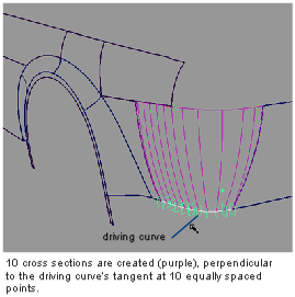
Cross-sections are created based on a driving curve you specify, and the Num Planes option. Points, equally spaced by arc length, are placed on the curve to correspond to the number of sections. A plane is then defined perpendicular to the curve’s tangent at each of these points. The cross-sections are created where the planes intersect the geometry.
The driving curve can be a free curve, a curve-on-surface, or a surface edge or isoparm.
Cross sections can be
created by using the Evaluate > Cross Section  tool, or by using the Cross
Section Control tab in the Modeling control panel.
tool, or by using the Cross
Section Control tab in the Modeling control panel.
When using Evaluate > Cross Section , you have to adjust the
cross section options every time you select new objects. The cross
sections are created as real geometry (NURBS or section data).
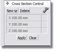
With the Cross Section Control tab, you can define groups of cross sections with specific characteristics, apply them to any geometry at any time, and even save them with your model. However, these cross sections are “visual” only (no geometry is created).
option window, and clicking Go.
To create Axis Aligned (X, Y, Z) geometry cross sections
❒, to open the option window.
Purple cross sections appear on the geometry, corresponding to the parameters set in the option window.
See Evaluate > Cross Section for option details.
To create Picked Reference geometry cross sections
❒, to open the option window.
Cross sections appear on the geometry, where it intersects the selected planes/section data.
 to sort out your cross sections
into different layers, according to the plane they lie in (X, Y,
Z or Other).
to sort out your cross sections
into different layers, according to the plane they lie in (X, Y,
Z or Other).
To create Radial geometry cross sections
❒, to open the option window.
Small planes, equally spaced by arc length, are displayed on the curve(s), corresponding to the number of sections. The planes are perpendicular to the curve’s tangent at each location.
Cross sections appear on the geometry, where it intersects the planes.
To use default cross sections from the Control Panel
 or
or  (Windows) or
  (Mac) key.
See Cross Section Control window for details.
These cross-sections apply to your entire Alias session.
To create and name a group of visual cross sections
The cross section appear in green and the Cross Section Control window opens.

 (Windows) or
  (Mac).
The new name for the cross section group is displayed in the control panel.
These user-defined cross-sections can be applied to any surface(s) or meshe(s) and are saved with your model.
The cross section group appears in gray in the Control Panel. It can then be applied to obejcts in other stages.
The default group will remain in the Control Panel even after you exit and re-launch Alias. To delete it, you must select it and press the Delete button.
To change the visual cross section settings
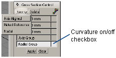
You can only modify the settings for Axis Aligned cross sections. In the Cross Section Control window, do the following:
To create and change a deviation comb on a visual cross section
The deviation combs appear in green on the model.
A Curvature Scale slider and Lock Curvature Scale checkbox appear in the Cross Section Control window.
 ).
).
To show or hide curvature plots on existing visual cross sections