In the pre-processing phase, the RayCaster:
In the rendering phase, the RayCaster loops through each pixel of the new image and calculates:
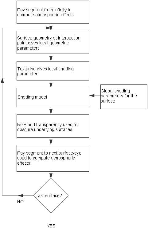
The final step of combining all the intersected triangles into a final color is complex.
If the ray intersects more than one triangle, the list of intersections is sorted by distance from the camera and processed from back to front. The renderer builds the final color and transparency by combining the colors and transparencies of each triangle, along with the atmospheric effects between the triangles. See the Procedural Textures and Natural Phenomena section of the SDL Reference Manual for more information on how these colors are calculated and combined.
This illustration shows the complex process by which the renderer combines the colors of the intersected triangles. It does not show the additional complexities introduced by motion blur.
The following illustration shows an example of how both the surfaces and ray segments are used to calculate the color and transparency of a pixel.
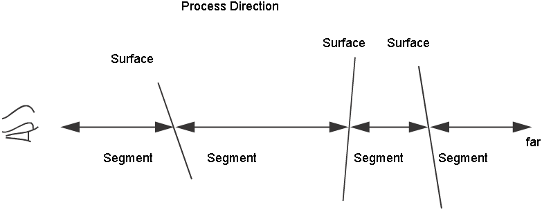
To calculate the ray illustrated above, the renderer starts with the color and transparency of the background. Then it calculates the atmospheric effects of the rightmost ray segment (the segment between the farthest surface and the background) and adds them to the color and transparency of the background. Then it adds the color and transparency of the farthest surface, then the next closest, and so on. Note that if any of the surfaces are opaque (transparency 0), the color information of farther surfaces is lost, since the opaque surface completely obscures the surfaces behind it.


