In keeping with the classic model construction method detailed at the beginning of the tutorial, you will now develop surfaces using the center line.
Using the selected curve in conjunction with
the Surfaces > Draft Surfaces > Draft/Flange  tool, you will be able to
quickly create a surface. The Draft tool
is a fast and easy way to create surfaces for defining the initial
shape of the model. In general, surfaces should be used, instead
of curves, to define the initial shape of a model. The surfaces
constructed in this tutorial, created using the Draft tool,
act as guides, or helpers, to produce the final, more professional
surfaces.
tool, you will be able to
quickly create a surface. The Draft tool
is a fast and easy way to create surfaces for defining the initial
shape of the model. In general, surfaces should be used, instead
of curves, to define the initial shape of a model. The surfaces
constructed in this tutorial, created using the Draft tool,
act as guides, or helpers, to produce the final, more professional
surfaces.

As long as the layer is highlighted in yellow, all new geometries will be assigned to that layer.
tool to open the option box.
 .
.
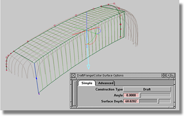
The Surfaces > Draft Surfaces > Draft/Flange tool can create a flat surface
from a curve, a surface edge, a curve-on-surface, or an isoparametric
curve.
The draft surface consists of an angle, a
length, and a direction – each of which is related to the current
construction plane and can be manipulated in the Draft Surface Options
box. Additionally, the Surfaces > Draft Surfaces > Draft/Flange tool produces a manipulator (a
big cross) for changing the direction and angle of the surface.
Another smaller manipulator is also produced that features a blue
circle and a red flag at the end. The red flag changes the length
of the draft while the blue circle changes the angle. Each manipulator allows
values to be typed into the Prompt line at the top of the screen.
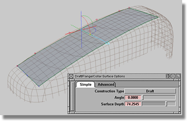
You can choose Flange by clicking the Draft button adjacent to the Construction Type option.
Flange is similar to Draft but the calculation of the direction is different. When a surface related object (an edge, a curve-on-surface, or an isoparametric curve) is selected, the normal of the surface is used to calculate the direction of the flange.
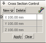
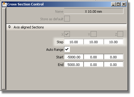
In the option window, there are three values for the Step option (X, Y, and Z). Make sure that the draft Step values equal the Step values for the scan line – for our model, the draft Step values should be set to 10.
To complete this section of the surface modeling process, create the next draft surface by choosing the edge of the previous draft. The new draft surface will have to follow the Z-direction.
Continue using the Draft tool to create a new surface