A theoretical model is a trimmed model without any fillets. The model has sharp, true edges. By examining a variety of consumer products, it is possible to see how fillets are the prominent aspect of the design. The fillets are said to flow from the theoretical model. As well, if you rotate a completed model in the sunlight, note how there are strong character lines highlighted by the sun – these lines define the shape of your model. To achieve fluid fillets and strong character lines, the quality of the theoretical model must equal the expected quality of the finished model.
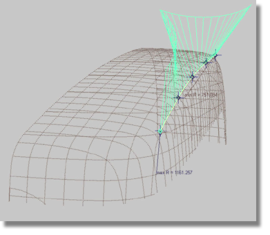
At this point in the tutorial, the model has a pointed theoretical line that was determined by creating the two draft surfaces. Examine the theoretical line and the two surfaces to see how closely they fit to the scan lines. To achieve a better result, try adjusting the length of the first draft surface and the angle of the second draft surface.
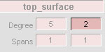
In regards to fitting the top surface, because the top surface is flat it will need to be shaped in order to fit to the scanned line. To shape the top surface, delete the construction history (draft), increase the flexibility (degree) of the surface, and direct model the surface.
To increase the degree of a surface
 .
.
 (Windows) or
  (Mac).
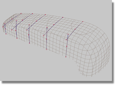
The top surface now has a Degree value of 2 in the V-direction and ensures the flexibility required to direct model the surface. To execute the direct model process, move the hulls and single CVs in such a manner that the green cross-section fits flush to the scan lines. At the same time, the second draft surface still has history and will always update when changes are applied to the top surface. When modeling the top surface, remember to check for symmetry issues.
 tool.
tool.
You should see a collection
of blue lines that highlight the surface as being symmetrical to
the plane at the Y0 position. The Object Edit > Align > Symmetry Plane Align tool created history that
will maintain the symmetry of the surfaces. If
you move the CVs of the first two hulls in the Z-direction, the
corresponding CVs will follow. Before using the tool, make certain
that the Project for Position option
is activated in the Symmetry Plane Align tool’s option box.
The objective of this section of the tutorial is to find the theoretical line by using simple techniques involving simple surfaces. The first priority should be to fit both surfaces to the scan lines, and then examine the theoretical line from a number of views.
To examine the theoretical line
 tool).
 menu item.
Compare your theoretical line to the views detailed below.
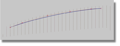
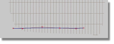
The theoretical line looks good from the side view.
However, the theoretical line does not look very good from the top view. Remember the criteria of the CV distribution in the curve-fitting section.
If the side and top views are acceptable, this is not a guarantee that the Perspective view is acceptable as well. As a basic rule, you must examine the theoretical line by tumbling the line in the Perspective view similar to the images below.
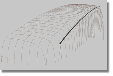
In the image below, note that the viewing position makes the theoretical line appear concave.
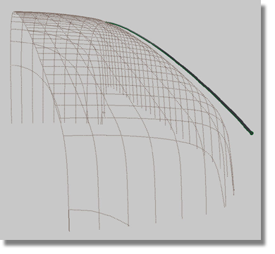
In the image below, note that the viewing position makes the theoretical line appear convex.
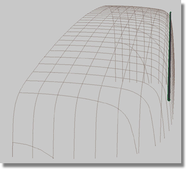
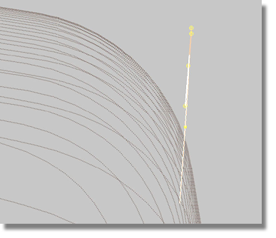
When tumbling between the concave and convex extremes, there must be a specific position where the view of the theoretical line has planar characteristics. See the image below for an example.
To achieve planar characteristics
for the theoretical line that resemble the image above, pressure
the curve using the Curve Edit > Curve Planarize  tool.
tool.
If technical restrictions
do not allow for the use of the Curve Edit > Curve Planarize tool, proceed with your
existing theoretical line. The technique of pressuring curves is
not a fixed rule, but rather, a guide for helping to define the
feature lines that dominate the shape of a model.
Criteria for the theoretical line
Solutions for meeting the theoretical line criteria
A theoretical line is more than just a curve. A theoretical line, in a wider sense of the definition, relates to the edge of a surface. When scan lines are absent, it is a difficult task to model from a curve because the theoretical line will have no scan lines to act as guides. When working with surfaces that are close to the scan lines, the edge of the surfaces will show the theoretical line.
At this point in the tutorial, your duplicated curve should be fairly close to the theoretical line. However, the planar criterion is not fixed and it will require a new function to correct the issue.
tool to produce the option
box.
| Set this parameter... | To this value |
|---|---|
| Default projection plane | Best |
| Lock ends | on |
| Keep originals | off |
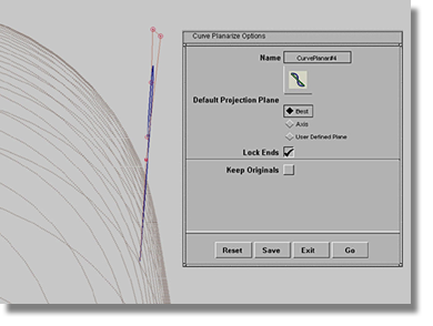
The Curve Edit > Curve Planarize tool produces a new curve
that differs slightly from the original in that it fits correctly
to the plane. If required, modify the new curve using the Control
Panel > Evaluate > Move CV tool. Because the new curve was
generated with the Curve Edit > Curve Planarize tool, the curve will remain
planar.
Establishing a fundamentally sound theoretical line is crucial to the success of the surface modeling project. The theoretical line provides the foundation for the construction of the surface model. As well, remember that it is equally important to maintain a smooth theoretical line in order to construct quality fillets.
Another method for creating a theoretical line involves the use of blend curves. While blend curves are a fast procedure and offer a high degree of history, they also lead to errors in the model. Because blend curves produce multi-span curves, the fundamental base for the entire surfacing process can be damaged. As a general rule, the geometry, or number of spans in a model, should always be kept to a minimum to ensure professional results.
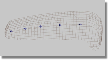
Fit curves to some scan lines. Extend the curves so that they intersect.
Create geometry points on the intersections. Double-click the Curve Edit > Curve Section tool and set the options as follows.
| Set this parameter... | To this value |
|---|---|
| Sectioning mode | Slice |
| Slice creation mode | Insert points |
| Sectioning criterion | Geometry |
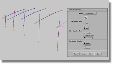
Create a blend curve by selecting all geometry points. Check the blend curve in the Control Panel to determine the number of spans and degrees. A multi-span curve has been produced. The blend curve is the theoretical line.
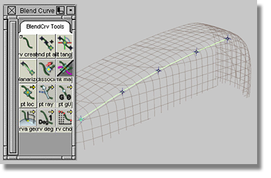
Examine the curvature plot of the blend curve, and then planarize the curve.