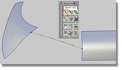
To create a blend curve between the edges of two surfaces, but not at the corners, snap the blend points to the surface. The resulting planar blend curve will always contain geometry constrained blend points and will have the curvature continuity of the reference surface.
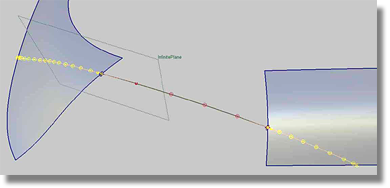
For a better understanding of the geometric curvature type, create a construction plane using three points snapped to the blend curve. Then, in the Control Panel, specify and calculate the sections in such a manner that the intersections between the surfaces and the construction plane appear as curves.
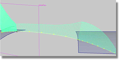
Both the intersection curves and the blend curve can be analyzed with the curve curvature tool. The curvature comb, as seen in the image below, details that the blend curve is planar and is curvature aligned to the two curves created by the intersection between the construction plane and both surfaces.
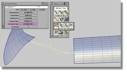
Another option for aligning a blend curve to more than one surface is to use the parametric constraint that employs the U/V directions of the surfaces. The parametric method is very useful when creating transition surfaces that must follow the parameter flow of both surfaces. To achieve this behavior, select the blend points first, then choose the Geometry type by clicking the BlendCrv Tools > Constraint Interpolation Direction > Blend Constraint Interp Geometry tool. Using the parametric method, a blend curve aligns to the appropriate isoperimetric line that represents the current U/V direction. In the Information Window, the Curvature type changes to PARAMETRIC.