Mastering the Object Edit > Align > Align 2008  tool is integral to the art
of constructing quality surfaces. Typically, the Align tool
is used in direct modeling methods.
tool is integral to the art
of constructing quality surfaces. Typically, the Align tool
is used in direct modeling methods.
The Align tool connection types
The rules are the same when aligning either surfaces or curves. But, the alignment of surfaces is more complex in detail and variations. For this reason, the following examination of the Align tool will deal specifically with the alignment of surfaces. The information gained from this tutorial can easily be adapted for aligning curves.
Basics - Simple and Advanced Mode
The Align tool’s option box features a simple and an advanced mode. To master the Align tool, it is necessary to work with the advanced mode but to reduce visual clutter, some of the images in this tutorial use the simple mode.
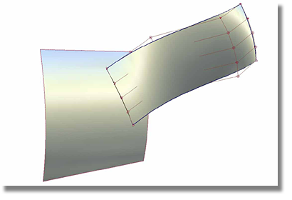
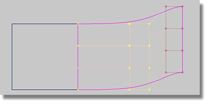
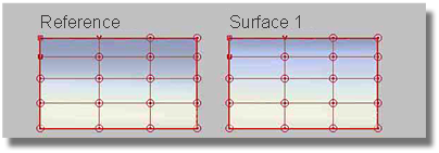
An alignment situation usually features a reference geometry (a curve or surface) and a geometry that is to be aligned. Within the confines of this tutorial, the reference geometry will be referred to as “the Reference” and the surface to be aligned will be referred to as “Surface 1".
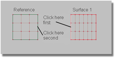
The selection algorithm requires that Surface 1 should always be selected first. It is important to note that when selecting Surface 1, the end of the geometry closest to the point of intended alignment should be selected. In situations where the Reference is a surface, the Reference edge must be clicked explicitly.
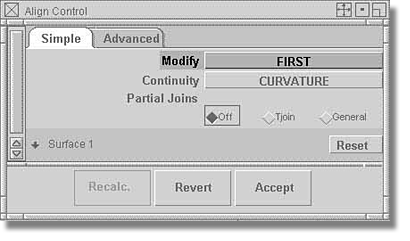
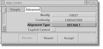
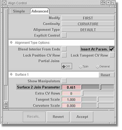
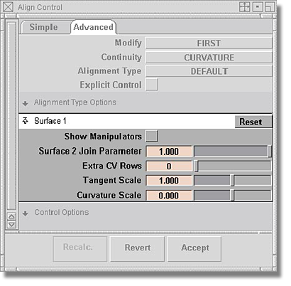
In most cases, the Reference remains at a fixed location, leaving all modifications to be enacted on Surface 1. To restrict the modification of the Reference, set the Modify option to FIRST as shown in the image below.
When using the Align tool, it is impossible to use the Edit > Undo command found in the Surface main menu. The Align tool does, however, offer its own undo functionality that is executed via the Revert button found in the tool’s option box.
As long as Surface 1 has an associated history, the Revert button steps the alignment procedure back to the last freeze point, or to the beginning of the procedure.
Clicking the Accept button freezes the alignment procedure.
The Continuity option dictates the quality of the alignment.
The execution of the alignment procedure changes the CV distribution of Surface 1. The number of influenced CVs depends on the quality set in the Continuity option.
The first and the second CV rows will be adjusted. The second row is responsible for achieving TANGENT continuity.
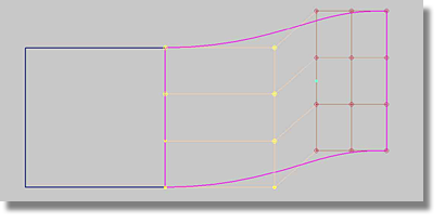
In addition to the first and the second rows, the third CV row will be moved.
Depending on the quality of the selected continuity, the influenced rows are always highlighted in yellow.
Within the Alignment Type option, there are a number of settings that dictate the specific CV distribution on Surface 1.
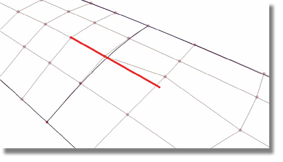
An examination of tangents will help to foster a better understanding of CV distribution.
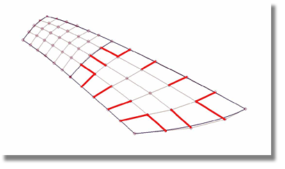
In the above image, the red (bolded) lines are tangents. In basic terms, a tangent is the line that connects the first CV of an edge (the endpoint of a curve) and the second CV.
When aligning surfaces by their edges, there are two criteria that must be considered.
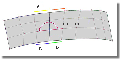
In this method, the tangents of each surface are in line.
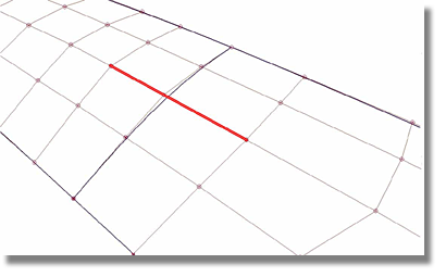
The above image shows two surfaces with colinear tangents.
The above image shows two surfaces with broken colinearity.
The Reference has a specific CV distribution that is determined by the lengths of the tangents. Similar tangent length ratios must be considered for Surface 1 when executing the alignment procedure. The tangent length ratios of Surface 1 must be fixed to those of the Reference.
To manage the alignment methods, Surface offers an Alignment Type option that contains the following settings.
The DEFAULT setting is typically used when aligning the edges of two surfaces. In general, the DEFAULT setting produces an ideal alignment in terms of a well-balanced geometry (the CVs are lined up in a colinear fashion). As well, Surface 1 tangents will have the same length ratio as found in the Reference.
Length of A / Length of B = Length of C / Length of D
The DEFAULT setting often executes dramatic changes to the CV distribution of Surface 1. As a result, discontinuity in terms of equal length ratio of tangents at the Reference will be visible on Surface 1.
Similar to the DEFAULT setting, the COLINEAR setting is typically used when aligning the edges of two surfaces. But while the tangents are fixed colinear, the tangent length ratios are not fixed, allowing the tangents to remain independent.
The colinear setting is used primarily to align a surface with the Reference when the two surfaces have widely different CV distributions.
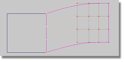
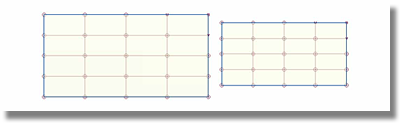
In the following three images, the Reference is left-justified while the Surface 1 is right-justified. The three References have a rectangular CV distribution while the three Surfaces 1s have a radial CV distribution.
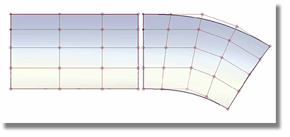
Using the DEFAULT setting, both alignment criteria will be fixed. Colinearity is maintained, and Surface 1 and the Reference have the same tangent length ratio. However, the radial criteria of Surface 1 will be destroyed.
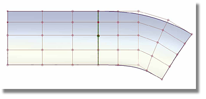
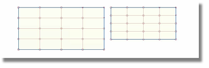
Using the COLINEAR setting, the tangent length ratios will not be fixed, but colinearity will be maintained.
In situations where the DEFAULT and COLINEAR settings are employed, the impact on Surface 1 is often significant. As a result, in order to use these two options, the Reference must have an immaculately clean CV distribution.
To provide for a measure of flexibility, Project alignment offers a lesser degree of impact on the CV distribution of Surface 1 when creating the required continuity. While Project alignment can match the required levels of continuity, this setting cannot create colinearity which is essential to achieving high-end surface quality.
When using the Project alignment setting, each influenced CV moves in the direction of the tangent plane normal that is related to a particular CV.
When following the edge of a surface, the CV setup required to create a tangent plane is in a constant state of change. In general terms, this means that the tangent plane on every point along the surface edge is different. During the Project alignment procedure, each CV of Surface 1 moves in a different direction.
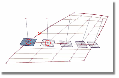
The image below features five tangent planes. The tangent plane on the far left was created using the circled CVs. Each tangent plane has a normal vector and each CV associated with Surface 1 moves in the direction of the normal vector of the appropriate tangent plane.
Project alignment can be used for aligning surfaces along their edges, as well as, for aligning a surface into the inner portion of another surface.
DIRECTIONAL alignment is primarily employed to align Surface 1 to an inner part of the Reference. In using this method, the three previously detailed criteria (Colinearity, Tangent Length Ratios, and ALIGN BY PROJECT) are nullified.
By setting the Alignment Type option to DIRECTIONAL, the movement of CVs are restricted to the direction the user has selected in the option box. As a result, when viewing from the pre-defined direction, the CV distribution will remain the same.
The alignment of Surface 1 to the inner part of the Reference requires that a curve-on-surface be employed as the Reference. Because of the high number of spans (parameterization) associated with a curve-on-surface, Explicit Control will have to be enabled. This ensures that Surface 1 will maintain the same number of degrees and spans that existed in the surface before the execution of the alignment process.
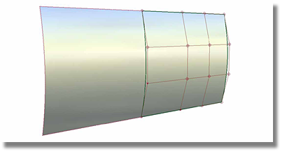
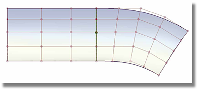
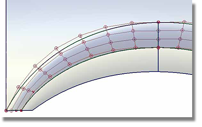
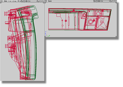
The image below typifies a situation common to automobile design - the wheel opening. With the CVs of the transition surface perfectly lined-up, the goal is to align the transition surface to the side surface by curvature.
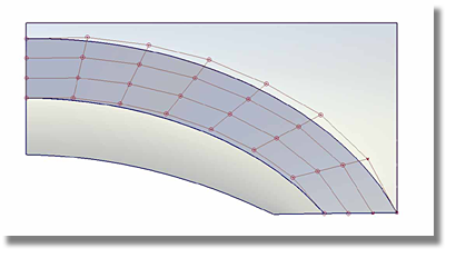
When using the ALIGN BY PROJECT setting in the wheel opening scenario, the CVs of the second and third rows move in the direction of the tangent plane associated with each CV which could result in substandard CV distribution as depicted in the image below.
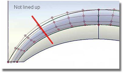
When viewed from the side, the CVs are no longer lined-up. Using the DEFAULT alignment setting will produce the same results. In fact, both the ALIGN BY PROJECT and DEFAULT alignment settings cannot guarantee a strictly radial CV distribution.
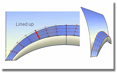
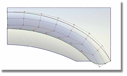
The solution to the wheel opening scenario is to restrict the CV movement to the Y-direction. This can be achieved by using the DIRECTIONAL setting.
This setting aligns the second and third rows of the surface in a dictated direction. This direction is always oriented 90 degrees to the curve-on-surface in use.
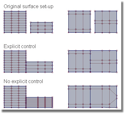
The following images depict the before and after state of a surface when using PERPENDICULAR TO EDGE alignment.
By enabling the Explicit Control toggle, the original parameterization of the patch is maintained throughout the alignment procedure. (Parameterization is defined as the number of degrees and spans of a curve, as well as the initial position of the CVs).
Situations that require Explicit Control
The Blend Interior From Ends option is associated with the Continuity setting TANGENT. When attempting to create curvature, the third CV row responsible for curvature will not be influenced by this option. Instead, this option pressures the second CV row of Surface 1 along a pre-defined line that is an interpolation of the first and the last CVs of the second row of Surface 1.
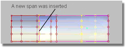
The Insert At Parameter toggle should be enabled when sliding Surface 1 onto the Reference. Surface 1 can be moved on top of the Reference by using the Surface 2 Join Parameter found in the Surface 1 chapter. Enabling the Insert at Parm toggle inserts an isoperimetric line at the Reference to help fix the position of Surface 1 on the Reference.
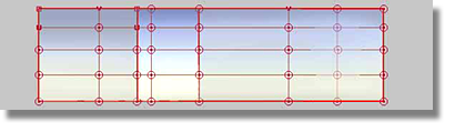
This arrangement is most beneficial when constructing conceptual work in which the surfaces are not fixed.
Partial Joins involve the management required to align two surfaces whose edges differ in size at the line of connection. The Partial Joins option does not influence the Alignment Type option.
The two settings used to create partial joins are Tjoin and General.
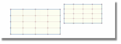
The image below shows a situation where both the Tjoin and General settings can be effective.
The General setting creates a segment at the point where Surface 1 joins to the corner point of the Reference surface.
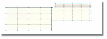
When using the General setting, there are two other options (Modify Interior Allowed and Attach Hardness) that allow for further refinements to the shape of Surface 1.
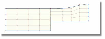
The Tjoin setting lines-up the corner of Surface 1 with the Reference surface without creating a new segment.
The Surface 1 chapter contains the options used in the management of Hull distribution across Surface 1.
Depending on the selected quality, the influenced row can have a maximum number of 3, but by incorporating extra CV rows, the number of influenced rows can be extended to achieve a smoother CV distribution in the interior of Surface 1. The additional row(s) will be highlighted and moved in keeping with the restrictions of the Continuity setting (POSITION, TANGENT, and CURVATURE).
To scale the Hulls, the Tangent Scale and Curvature Scale sliders are available to the user. To further influence the movement of extra rows, the Decay Degree slider can be manipulated.