The option box associated
with the Surfaces > Surface Fillet  tool contains a simple and an
advanced mode. In order to master the Fillet tool, it is beneficial
to work exclusively in the advanced mode.
tool contains a simple and an
advanced mode. In order to master the Fillet tool, it is beneficial
to work exclusively in the advanced mode.
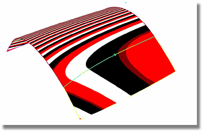
The Fillet tool, in general terms, creates a fillet surface between two surface clusters. A surface cluster can include more than one surface.
The Fillet tool requires a tangent continuity between the surfaces of each cluster.
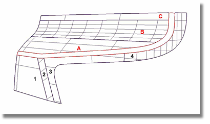
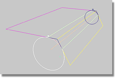
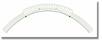
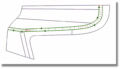
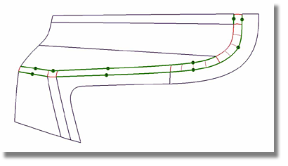
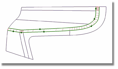
Selecting surfaces for use with the Fillet tool
If the selection process was a success, and the options (such as the size of the radii, or the direction of the major normal vectors) are without conflict, the fillet surface is created.
If the fillet surface creation fails, an error message will appear in the Information Line located at the top of the screen. The details of the failure may include an illogical set-up of the major normal vector which can be easily corrected by manipulating the blue arrows.
The Construction
Type option defines the kind of input required to create
the fillet surface. The three settings available in this option
are CONSTANT, VARIABLE,
and CHORDAL. To create a freeform
fillet (blend), choose Surfaces > Multi-Surface Blend > Freeform Blend  .
.
This setting requires a radius input to create the fillet surface. The resulting fillet surface has the same radius along the entire surface.
This setting also requires a radius input to create the fillet surface. However, the VARIABLE setting allows for the possibility of creating a fillet surface that uses multiple radii along the length of the fillet.
A manipulator is available for interactively setting the variable radii.
The manipulator has an orange line and circles that specify the different radii.
Two methods for creating new circles
 to create a new circle and
hold down the middle mouse button to move the circle interactively
along the orange line.
to create a new circle and
hold down the middle mouse button to move the circle interactively
along the orange line.
 to create a new circle on
the orange line and press the to change the size of the
radius.
to create a new circle on
the orange line and press the to change the size of the
radius.
Methods for modifying existing circles
 key and click the circle
with any mouse button.
. Holding down the changes the radius of the
selected circle.
.
key and click the circle
with any mouse button.
. Holding down the changes the radius of the
selected circle.
.
In order to use this setting, specify the distance between the entry lines of the fillet. The distance measurement will remain constant across the entire fillet and will result in a fillet composed of various radii. The radii are automatically calculated.
The CHORDAL setting is most useful when the continuity between both surface clusters becomes tangent.
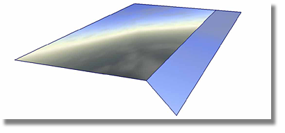
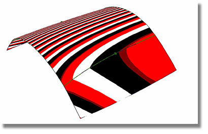
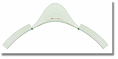
In the case shown above, any method that uses pre-defined radii will always create triangle surfaces, as shown below.
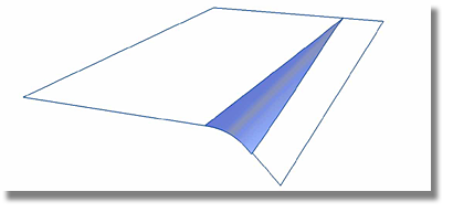
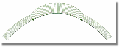
As can be seen below, the CHORDAL setting maintains a constant distance between the fillet entry lines.
This option defines the shape of the fillet surface. The three main settings available in this option are CIRCULAR, LEAD, and CURVATURE.
This setting creates a fillet surface that features a circular cross-section that is tangent to both surface clusters. TANGENT Continuity is maintained with the surfaces on either side.
As shown above, after using the CIRCULAR setting a curvature comb reveals a visible curvature break. As depicted in the image below, this curvature break will be reflected in the finished model by an abrupt change in the highlights of the surface.
This setting creates a fillet surface that along with the Center Radius and Tangent Offset options define the point of contact with the inner surfaces. TANGENT Continuity is maintained with the surfaces on either side.
The Center Radius option defines the radius at the peak.
The Tangent Offset option defines the contact with the Reference.
As shown by the curvature plot in the above image, the LEAD option produces a visible curvature break. But, as depicted in the image below, the curvature results of the LEAD option provide for a better highlight than the CIRCULAR option.

The LEAD setting requires the input of two different radii.
The Tangent Offset option associated with the LEAD setting specifies the distance between the intersection line of the two sets of surfaces and the contact lines (the lines along which the new fillet surface touches the surfaces on either side). The radius for the contact line and the value for the Center Radius option can be input into the Tangent Offset option.
The Center Radius option associated with the LEAD setting specifies the radius at the peak of the fillet.
The Specify option associated with the LEAD setting has two methods for radii input.
The KNEE RATIO setting in the Specify option is for detailing the ratio between the Center Radius and the Tangent Offset distance.
KNEE RATIO = Center Radius / Tangent Offset
Since the two numbers result from different lead distance measurements, it does not matter in which order they are specified.
The CURVATURE setting creates a fillet that has CURVATURE Continuity on both sides of the surfaces.
This setting provides optimal continuity. As shown in the image below, a final surface model built with the CURVATURE setting is not burdened with a visible contact line.
This option controls the span division within the new fillet surface. There are two settings within this option, DEFAULT and ONE-PER-BOUNDARY.
By using the DEFAULT setting, a fillet surface is created with the minimum number of spans required to fix the tolerance. The placement of the spans follows internal mathematical rules that are independent of the surface layouts of both surface clusters.
By using the ONE-PER-BOUNDARY setting, spans are inserted into the fillet surface that correspond to the boundaries of both surface clusters. Additional spans are also inserted into the fillet surface to meet the requirements of the tolerance. As a result, the ONE-PER-BOUNDARY setting usually produces less spans than the DEFAULT setting.
When using the ONE-PER-BOUNDARY setting another option is available. The Single Surface toggle dictates whether or not the inserted spans at the corresponding boundaries will divide the fillet surface in single pieces. If the Single Surface option is not enabled, the fillet surface is created as one object that is sub-divided into separate surfaces.
By enabling the Single Surface option, a fillet surface is created that is one object consisting of one surface.
The Undo All button is located at the bottom of the Surface Fillet Control box. When creating a fillet surface that requires the incorporation of multiple surfaces, an abundance of geometry could be created such as curve-on-surfaces on each surface cluster or single fillet surface pieces. If the fillet needs to be deleted, it is much easier to select all of the geometry first.
A recommended method
for selecting all of the geometry is to reactive the Fillet tool
by using the Object Edit > Query Edit  tool. Once the Surface Fillet
Control box has been reactivated, click the Undo
All button to delete the complete fillet, including any
curve-on-surfaces.
tool. Once the Surface Fillet
Control box has been reactivated, click the Undo
All button to delete the complete fillet, including any
curve-on-surfaces.


