tool to create a new construction
history.
tool to create a new construction
history.
To continue building the main surfaces, you will use some of the previously fitted curves to construct the front and rear surfaces.
 tool to produce the option box.
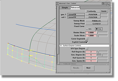
| Set this parameter... | To this value |
|---|---|
| gen. 1 (curve #28) | Continuity set to Position, Rebld off |
| rail 1 (curve #19) | Continuity set to Position, Rebld off |
| Sweep Mode | PARALLEL |
| Sweep Pivot | CLOSEST |
| Fixed Curve | RAIL |
| Rotate Xform | 0.0000 |
| Scale Xform | 1.0000 |
| Curve Segments | off |
| Explicit Control | on |
| U/VSync Degree | off |
| Rail Degree (U) | 2 |
| Gen. Degree (V) | 5 |
| Rail Spans (U) | 1 |
| Gen. Spans (V) | 1 |
A new method utilizing construction planes will be introduced to build the transition surface.
 tool. A 3-point plane will
be created.
tool. A 3-point plane will
be created.
 +
+  (Windows) or
  +
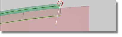
+  (Mac)), select a corner
point of the front surface to mark the centre of the new construction plane.
(Mac)), select a corner
point of the front surface to mark the centre of the new construction plane.
If a construction plane is
created using geometry (3-point plane, surface plane), the construction
plane will always have an associated construction history. Deleting
the geometry used to create the construction plane will also delete
the construction plane, even if the construction plane is assigned
to another layer. If you want to delete the geometry but maintain
the construction plane, delete the construction history of the construction
plane to achieve independence. If a number of construction planes
are required for the modeling process, each construction plane can
be named using the Windows > Information > Information Window  menu item.
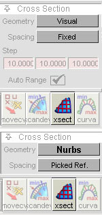
To intersect a construction plane with a surface
Changing the Geometry option to NURBS will create Nurbs curves on the reference surface. The Nurbs curves have a poor CV distribution, but offer a connection history to the construction plane.
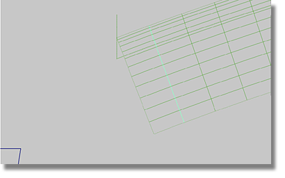
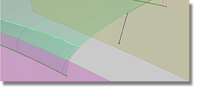
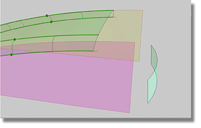
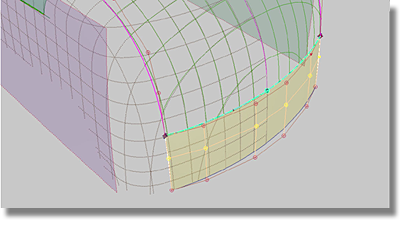
At this point in the process, your model should resemble the image below.
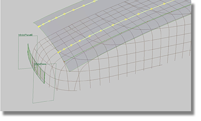
Before proceeding, it should be noted that the straight edge of the top surface could not be used to construct the transition surface. In the top view, the front surface displays a curved character that must flow through to the top surface. In order to transition the curved character of the front surface, apply a curve-on-surface shaped similar to the front surface.
To change the shape of an edge by trimming the basic surface
 tool).
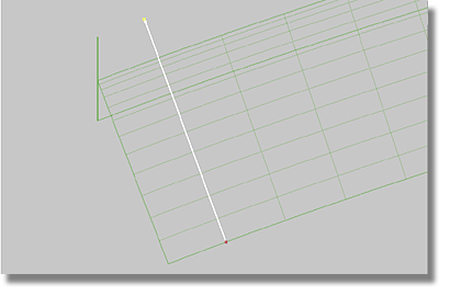
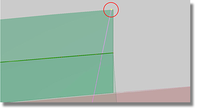
The model now has a curve-on-surface that defines the edge of the transition surface to be built later in the tutorial.
The imbalance between the curve-on-surface and the fillet surface may produce difficulties during the process of balling the corners. To minimize the difficulties associated with balling the corners, reshape the curve-on-surface along the isoperimetric line of the fillet surface.
 tool.
tool.
tool and select the fillet
surface, press the left mouse button, and slide the mouse horizontally
in the left direction to remove all of the isoperimetric lines.
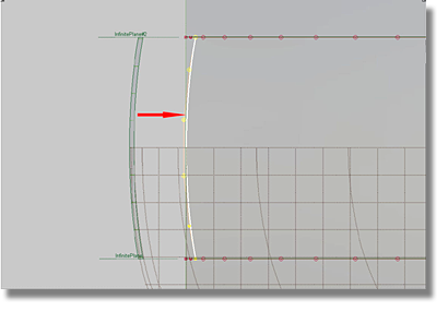
A new curve-on-surface is created that differs from the original straight edge of the top surface and has a better appearance in the side view.
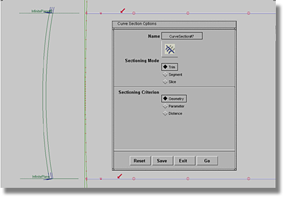
Both of the curves built by intersecting the construction plane with the top surface are too long and must be cut to match the curve-on-surface.
To cut a curve using reference geometry
 tool to open the option
box.
tool to open the option
box.
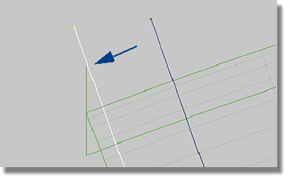
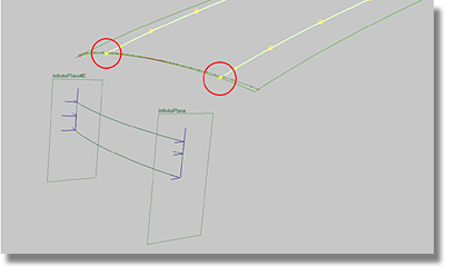
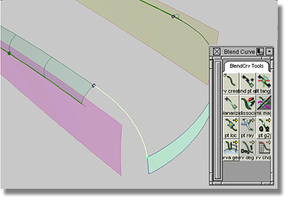
Before using the Rail tool, define two blend curves between the intersection curves and the front surface.
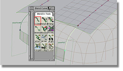
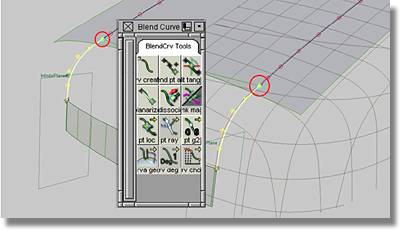
To use blend curves to define the edges of transitional surfaces
 tool and select the curves
and the edges using CRV snapping (press + (Windows) or + (Mac)).
tool and select the curves
and the edges using CRV snapping (press + (Windows) or + (Mac)).
By connecting a blend curve with a curve, the blend curve does not contain the curvature continuity required for the model. As a general rule, a blend curve connected to a curve will always contain POSITION Continuity G0. (Remember the previously completed curve-fitting section).
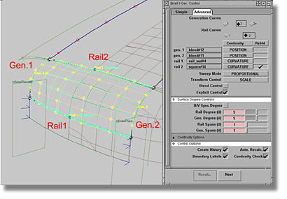
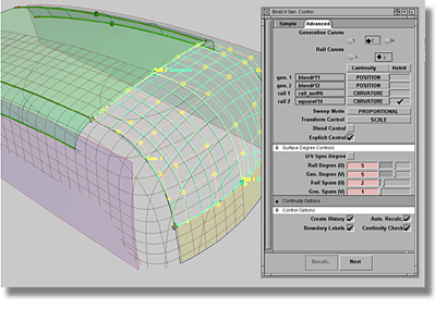
To use the Rail tool to create the transition surface
tool to open the option box.
| Set this parameter... | To this value |
|---|---|
| Generation Curves | 2 |
| Rail Curves | 2 |
| gen. 1 (blend#12) | Set Continuity to POSITION, Rebld off |
| gen. 2 (blend#11) | Set Continuity to POSITION, Rebld off |
| rail 1 (rail_surf#4) | Set Continuity to CURVATURE, Rebld off |
| rail 2 (square#14) | Set Continuity to CURVATURE, Rebld on |
| Sweep Mode | PROPORTIONAL |
| Transform Control | SCALE |
| Blend Control | off |
| Explicit Control | on |
| U/V Sync Degree | off |
| Rail Degree (U) | 5 |
| Gen. Degree (V) | 5 |
| Rail Spans (U) | 1 |
| Gen. Spans (V) | 1 |
| Create History | on |
| Auto. Recalc. | on |
| Boundary Labels | on |
| Continuity Check | on |
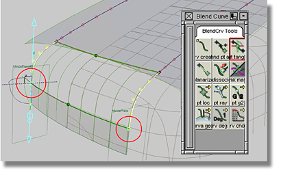
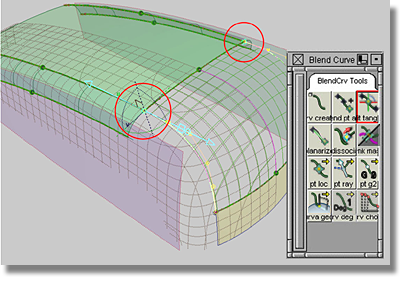
Activate the X-Cross-Sections of the new Rail surface. The updated Rail surface does not fit to the scan lines because the blend curves are flawed. To correct the problem, modify the blend curves at the same time to maintain the model’s symmetry.
 tool.
tool will produce a single
Locator that will be responsible for both selected blend points.
tool.
tool will produce a single
Locator that will be responsible for both selected blend points.
If the modification of the blend curve did not achieve the desired fit to the scan lines, examine the front and top surfaces to determine if further changes are required.
When modifying the front surface, use the direct modeling method (moving the CVs of the front surface). One of the consequences of modifying the front surface using direct modeling is that the construction history of the Rail surface will be lost. As well, because the front surface runs across the plane at the Y0 position, the symmetry will need to be maintained. (Keep in mind the rules for modifying CVs that run across the Y0 plane).
When modifying the top surface, remember that the top surface has a construction history that ties it to the fillet and side surfaces. As a result, modification of the top surface will be a time-consuming endeavour because the fillet surface will also have to be updated. To speed-up the modification process, postpone the recalculations by temporarily suspending the construction history. When you have found an acceptable modification, reinstate the construction history. Another restriction against modifying the top surface is that the edge of the top surface connects to the side surface, and as such, cannot be modified because the side surfaces are the references for the top surface.
How to reactivate the calculation
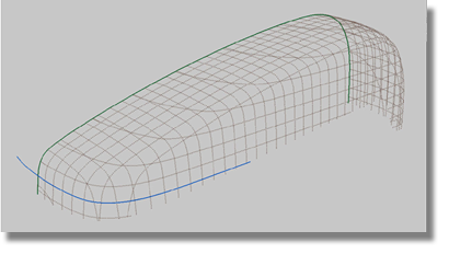
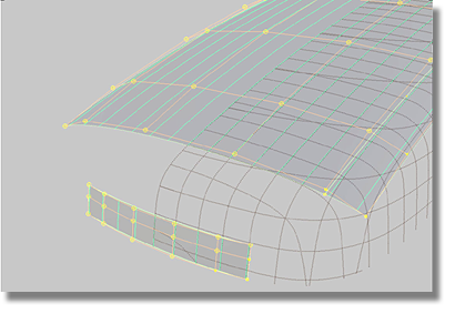
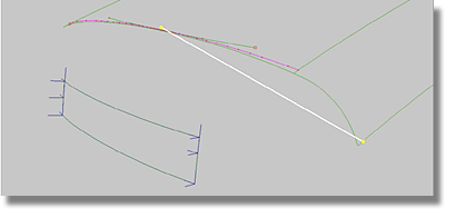
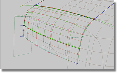
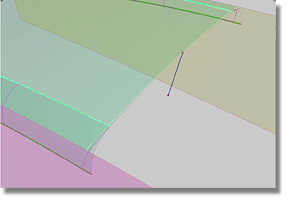
After finishing the front surface and the transition to the top surface, your model should resemble the image below.
![]()
Applying a Transition Between the Rear and Top Surfaces
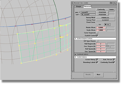
The rear surface will be constructed using a similar approach to that used in creating the front surface. A Rail surface will be constructed using two curves from the center line and a corresponding Z- curve.
To create the transition surface, you will use the fillet surfaces already created, but there will be no need to create construction planes or curves that intersect with the top surface.
Given the shape of the rear scan lines, the edge of the transition surface will be shaped to touch the top surface using a curve-on-surface.
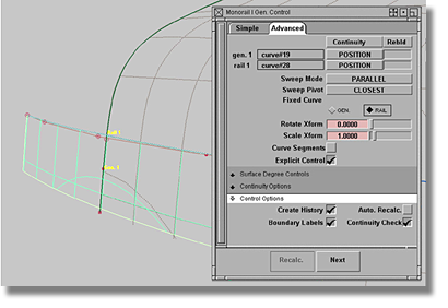
| Set this parameter... | To this value |
|---|---|
| gen. 1 (curve#57) | Set Continuity to POSITION and Rebld off |
| rail 1 (fit_curve#2) | Set Continuity to POSITION and Rebld off |
| Sweep Mode | PARALLEL |
| Sweep Pivot | CLOSEST |
| Fixed Curve | RAIL |
| Rotate Xform | 0.0000 |
| Scale Xform | 1.0000 |
| Curve Segments | off |
| Explicit Control | on |
| Rail Degree (U) | 2 |
| Gen. Degree (V) | 5 |
| Rail Spans (U) | 1 |
| Gen. Spans (V) | 1 |
| Create History | on |
| Auto. Recalc. | on |
| Boundary Labels | on |
| Continuity Check | on |
In this section of the modeling
process, you will build the transition surface over the Y0 plane
and maintain the construction history throughout the entire operation.
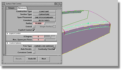
You will begin the construction by creating a fillet on the other
side of the model, but first, examine the options of the existing
fillet. In order to produce the options box for the existing fillet,
the Object Edit > Query Edit  tool can be used if the
construction history of the existing fillet has not been lost.
tool can be used if the
construction history of the existing fillet has not been lost.
tool.
 .
.
Now you are ready to create a curve-on-surface that will be the top edge of the rear transition surface. The curve-on-surface must have the curved character of the rear surface as seen in the top view.
To shape one edge of the rear transition surface
 tool).
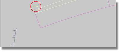
The resulting curve-on-surface could be split into two parts, one of which is highlighted. The entire curve-on-surface is not highlighted because there is a problem with the curve used for the projection.
To correct the curve and complete the curve-on-surface
To create blend curves between the rear surface and the fillets
 menu item).
tool.
menu item).
tool.
 to make the top surface
visible.
to make the top surface
visible.
| Set this parameter... | To this value |
|---|---|
| Generation Curves | 2 |
| Rail Curves | 2 |
| gen. 1 (blend#11) | Set Continuity to POSITION, Rebld to off |
| gen. 2 (blend#12) | Set Continuity to POSITION, Rebld to off |
| rail 1 (rail_surf) | Set Continuity to CURVATURE, Rebld to off |
| Rail 2 (square#14) | Set Continuity to CURVATURE, Rebld to on |
| Sweep Mode | PROPORTIONAL |
| Transform Control | SCALE |
| Blend Control | off |
| Explicit Control | on |
| U/V Sync Degree | off |
| Rail Degree (U) | 5 |
| Gen. Degree (V) | 5 |
| Rail Spans (U) | 2 |
| Gen. Spans (V) | 1 |
| Create History | on |
| Auto. Recalc. | on |
| Boundary Labels | on |
| Continuity Check | on |
Further adjustments may be required to achieve a better fit between the rear surface and the scan lines. To correct the errors, the Rail surface will have to be adjusted. However, there are a number of strategies that could be employed.
Strategies for adjusting Rail surfaces
The modification of the Rail surface will require the employment of all three methods. Before starting the modifications, consider the following factors that could determine the proper course of action.
Factors to consider when adjusting Rail surfaces
The proper course of action is to begin by modifying the blend curves.
To fit the transition surface by modifying the blend curves
tool.
The blend curve and the transition surface will update to reflect the modifications.
To fit the transition surface by modifying the rear surface
To fit the transition surface by modifying the top surface
The top surface is related
to two fillet surfaces and the front and rear transitions. When
modifying the top surface, the associated surfaces will also require
recalculations that could result in time delays. To avoid time delays,
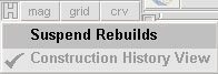
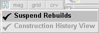
use the Windows > Information > History View  menu item to suspend the
recalculations during the modification process.
menu item to suspend the
recalculations during the modification process.
See the section entitled “The transition between the front and top surfaces” for the details concerning the suspension and reactivation of the calculations.
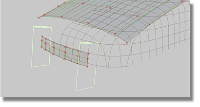
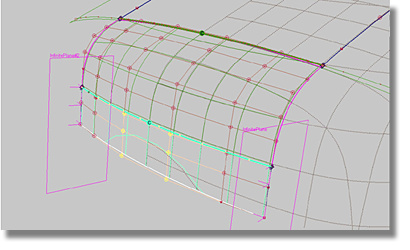
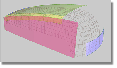
After finishing the modification to the rear transition surface your model should resemble the image below.
![]()