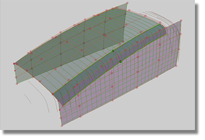
Arrange your screen as shown in the image below. Only the two side surfaces and the center line should be visible.
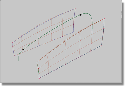
In the previous section, you created the side surfaces of the body to fit the length of the top surface and to be in line with the center line. In the image below, the small spheres denote the front and rear points of the top curve. As well, the image below clearly shows that the rear of the top curve has no clear connection to the side surfaces of the body.
To connect the rear of the top curve to the side surfaces of the model

 tool, project the created
curve onto the selected surfaces.
tool, project the created
curve onto the selected surfaces.
The Surface Edit > Create CurvesOnSurface > Project tool always projects the curve
onto the selected surfaces in the direction of the current view.
Working in the orthographic window while using the Surface Edit > Create CurvesOnSurface > Project tool requires some special considerations.
Using the Project tool in the orthographic window
To build the foundations of the top surface
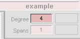
Examine the top curve created in the “Fitting curves to X-scans” section. For the top portion of the curve, note that a degree 4 curve was used. To achieve the same results with the current curve, increase the Degree values for both of the newly created curves.
Reshape both curves by employing the same methods used to fit curves to the X-scans.
Basic rules for modeling the CVs of curves across the Y0 plane
 tool to produce the options
box.
tool to produce the options
box.
| Set this parameter... | To this value |
|---|---|
| Curves | set all to FIXED Continuity, no Rebuild |
| Blend Type | LINEAR |
| 1-3 Boundary Blend | 0.500 |
| 2-4 Boundary Blend | 0.500 |
| Explicit Control | off |
| Max. New Spans | 0 |
| Insert at Midpoint | off |
| Colinear options for boundaries | Set all off |
| Create History | on |
| Auto. Recalc | on |
| Boundary Labels | on |
| Continuity Check | on |
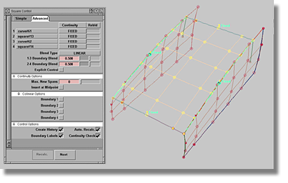
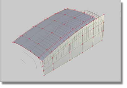
The newly created surface should be flat and match the length of the top curve of the center line. The next step in the process will be to shape the top surface to fit the scan lines. Because the top surface has a square history, modify the curves on the front and rear of the surface. Once the square surface is updated, check the shape of the surface and compare the results to the scan lines by turning on the cross-sections in the X and Y directions.
When fitting the top surface to the scan lines, it may not be clear as to where the surface has to deviate from the scan lines. To help define the area where the top surface has to fit the scan lines, use the X-curves created in the “Fitting curves to X-scans” section. Remember that the scan lines represent the finished model, including the fillets. At this point in the modeling process though, the theoretical model does not include fillets. Using the dimensions of the X-curves, you can determine the location of the fillets and where the top surface needs to fit the scan lines.
After obtaining an acceptable level of deviation to the scan lines, create the fillets to see if the surfaces are located in the right position. At this point in the modeling procedure, the fillets serve as an evaluation tool to help determine if the main surfaces are correct.
If the resulting fillets are not correct, the main surfaces and theoretical line can be further manipulated to achieve the desired results.
To create a fillet between two surfaces
 tool to produce the option box.
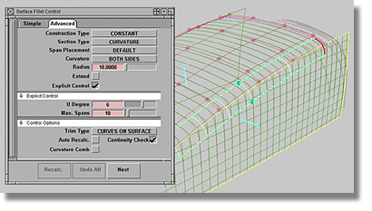
| Set this parameter... | To this value |
|---|---|
| Construction Type | CONSTANT |
| Section Type | CURVATURE |
| Span Placement | DEFAULT |
| Curvature | BOTH SIDES |
| Radius | 18 |
| Extend | off |
| Explicit Control | on |
| U Degree | 6 |
| Max. Spans | 10 |
| Trip Type | CURVES ON SURFACE |
| Auto Recalc. | off |
| Continuity check | on |
| Curvature Comb | off |
 .
.
If the main surfaces have an acceptable fit to the scan lines, the fillet surfaces should also fit to the scan lines. If the radius is unknown, experiment with the Radius option value. The objective is to find a solution that allows the fillet entry lines to obtain a close proximity to the endpoints of the blend curve that represents the connection between the top and side of the X-scan line.
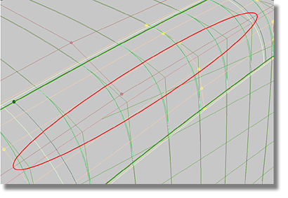
In the image above, the area has been marked where the fillet surface does not have an acceptable proximity to the scan lines. To correct the fillet surface, begin by examining both the top and the side surfaces. If either of the surfaces is found to be in error, corrections will have to be conducted. To reduce confusion in the view and speed-up the modification process, make the fillet surfaces invisible.
Factors to consider when making corrections to surfaces
To change the theoretical line by moving hulls
 from the menu.
.
from the menu.
.
 from the menu to make the
fillet visible again.
from the menu to make the
fillet visible again.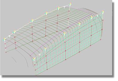
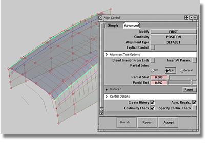
To construct a new construction history using the Align tool
If the construction history of the top surface is lost, the connection to the side surfaces will also be lost. To rebuild the construction history of the top surface, a new modeling strategy will be introduced to achieve the desired results. You can also use this strategy if you lose the symmetrical character of the side surfaces.
 tool to re-establish the
characteristics. The Curve Edit > Curve Planarize tool can be employed on
curves as well as surface edges, such as the theoretical line. When
using the Curve Edit > Curve Planarize tool, set the Default Projection
Plane to Best, and turn off the Keep Originals option. Repeat the
planarize process for the other side surface.
tool to re-establish the
characteristics. The Curve Edit > Curve Planarize tool can be employed on
curves as well as surface edges, such as the theoretical line. When
using the Curve Edit > Curve Planarize tool, set the Default Projection
Plane to Best, and turn off the Keep Originals option. Repeat the
planarize process for the other side surface.
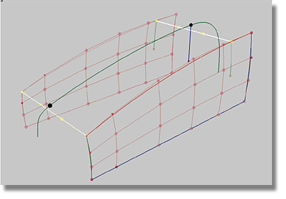
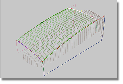
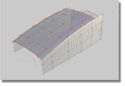
If all of the procedures of this section were successfully executed, your model should resemble the image below.