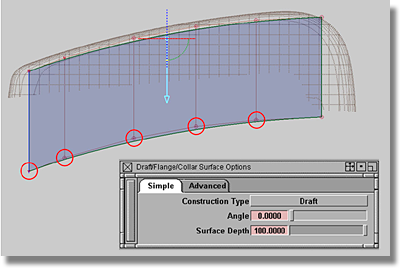
The extended theoretical line is the base for the side surface.
 (Windows) or
  (Mac) (this will activate
Magnetic Snap).
(Mac) (this will activate
Magnetic Snap). 
 to click near to the unselected
CV on the right-hand side.
to click near to the unselected
CV on the right-hand side.
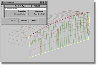
Having produced a surface in the Z-direction, the number of degrees will need to be increased to shape the surface in the Y-direction.
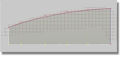
In the above image, the marked area denotes the area where the surface will fit to the scan lines. The marked area can be determined by examining the previously fitted curves. The overall surface must have a good CV distribution. As for the marked area, the surface must fit to the scan lines. It is a possibility that three hulls are not enough, in which case, the degree should be increased to 3. Also, at this stage in the development of the model, avoid moving single CVs as the surface could be damaged. Upon reaching the point where the model cannot be improved, switch the type of surface to gain more flexibility. But first, copy the edges of your current surface to create a square.
 tool to produce the option box.
| Set this parameter... | To this value |
|---|---|
| Duplicate type | No rebuild |
| Smoothing | off |
| Interactive | off |
| MinMax display | off |
| Auto Recalc | on |
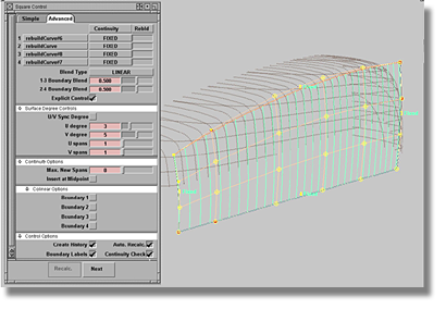
 tool.
tool.
| Set this parameter... | To this value |
|---|---|
| rebuildCurves | set all to FIXED Continuity, no Rebuild |
| Blend Type | LINEAR |
| 1-3 Boundary Blend | 0.500 |
| 2-4 Boundary Blend | 0.500 |
| Explicit Control | on |
| U/V Sync Degree | off |
| U degree | 3 |
| V degree | 5 |
| U spans | 1 |
| V spans | 1 |
| Max. New Spans | 0 |
| Insert at Midpoint | off |
| Colinear options for boundaries | Set all off |
| Create History | on |
| Auto. Recalc | on |
| Boundary Labels | on |
| Continuity Check | on |
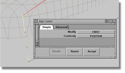
After the recent
modifications to the model, the theoretical line may need to be
adjusted. If adjustments to the theoretical
model are required, use the Curve Edit > Curve Planarize  .
.
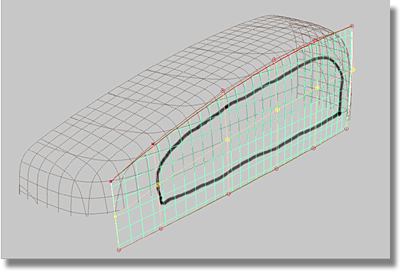
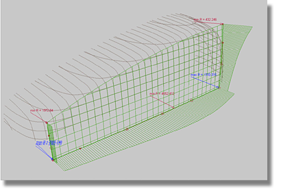
As for the square surface, the primary requirement is that it fit to the marked area of the scan lines.
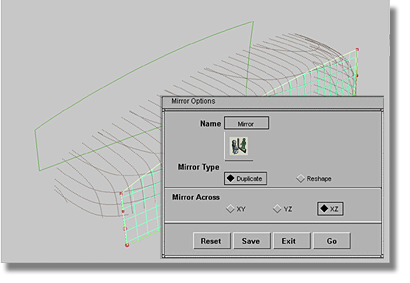
 tool to produce the mirror
options box.
tool to produce the mirror
options box.
| Set this parameter... | To this value |
|---|---|
| Mirror Type | Duplicate |
| Mirror Across | XZ |
The model now has two side surfaces, but they are not identical. The original side surface has a construction history while the mirrored surface does not. To correct this imbalance, delete the curves used to build the original square – the curves hold the construction history. When the side surfaces are identical (without history), they are complete for this section of the tutorial.
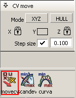
After deleting the curves, the only possibility to model both side surfaces is to use the direct modeling method. You will use the same techniques that were applied to the model when you used curves to modify the square surface. Remember, when applied to two symmetrical surfaces, the direct modeling method requires that corresponding CVs will have to be selected, movement in the X and Z directions must be driven from the Control Panel > Evaluate > Move CV tool, and movement in the Y-direction must be conducted using the non-proportional scale. In repeating techniques, you not only gain more experience but may also find new methods to complete the task.
Having completed the two side surfaces, the next step will be to complete the top surface.


