Creating blends between the main curves


To create the blends using blend curves

  1. Click and hold down the Y-scan layer button to open the menu.
  2. Choose Set State > Reference from the layer menu.
  3. Choose Curves > Blend Curve Toolbox to open the toolbox.

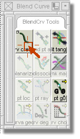
  4. Choose the BlendCrv Tools > Blend Curve Create tool from the toolbox. (Click the BlendCrv Tools tab to see the menu or click the icon).
  5. Place a blend point (the first point of the blend curve) on the endpoint of the top curve.
  6. Place the second blend point on the endpoint of the back curve.

    A straight line will appear between the top curve and the back curve.
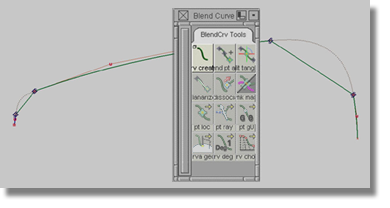
  7. Repeat Steps 4 to 6 for the other side of the curve.

    NoteThe number of blend points can be unlimited, but it should be understood that each new blend point increases the number of spans on the blend curve. Also, a blend point holds a vast array of information that defines the shape of the blend curve. A blend point is essentially a guide, or a point of reference, for a blend curve that could interact with a curve, a surface, an isoperimetric curve, or a curve-on-surface. To access the information associated with the blend point, open the Information window.

To use the Information window

  1. Choose the Pick > Point Types > Blend Point tool and select one blend point.
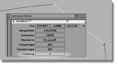
  2. Choose the Windows > Information > Information Window menu item.

The value for the Continuity option should be set to 0. Continuity is a measurement of how two surfaces or curves connect.

For the purposes of our model, the blend curve should appear as a bowed transition between the two scan lines. In order to change the blend curve, we will need to change the Continuity measurement to 2.