In this section you will learn how to:
After you have fashioned your model from the foam cube, scan the model’s surface to produce a series of scan lines that represent your creation. If the scan lines do not look exactly the same as the foam model, keep in mind that the model was handcrafted, and as a result, small surface degradations may have been created during the model’s construction. It is also entirely possible that the scanning device made errors due to a discrepancy in stated construction tolerances. Regardless of the cause of the errors, it should be understood that the primary role of the scan lines is to provide a guide for the dynamics of the model. Before beginning the surface modeling, use the scan lines to garner information about the model.
Similar to sketching on the foam cube, the first step in the surface modeling process is to create a center line based on the scanned input.
 tool.
tool.
 tool, the scan lines can
only be selected as curves, not sections.
tool, the scan lines can
only be selected as curves, not sections.
With all of the scan lines displayed, you might find that the model is cluttered. To make your work appear cleaner, isolate the scan line that represents the center line.
 and select the scan line
that represents the center line.
and select the scan line
that represents the center line.
 . All unselected scan lines
are hidden - only the selected center scan line is visible. (To
make the hidden lines visible again, choose ObjectDisplay > Visible
. All unselected scan lines
are hidden - only the selected center scan line is visible. (To
make the hidden lines visible again, choose ObjectDisplay > Visible  from the menu).
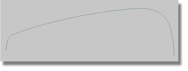
Commit these steps to memory – later in the tutorial you will be asked to isolate a particular scan line or make a layer visible or invisible.
You may recall that when
you were in the workshop you found it difficult to shape the center
line in one step. To complete the model, you shaped three main surfaces (the
front, middle, and rear) and completed the model by adding two blends.
Following the workshop example, fit a curve to the top part of the
center scan line. Use an automatic fitting algorithm, such as the Curve Edit > Fit Curve  tool, to undertake this
part of the project.
tool, to undertake this
part of the project.
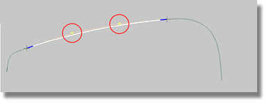
To fit the top part of the center line using the Curves > Fit Curve tool
![]()
 tool to produce the options box.
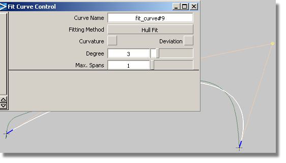
tool selects the entire
scan line, but initially you will be interested in selecting only
the top part of the curve.
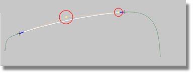
Your curve should resemble the above image. As you gain more experience with surface modeling, you will learn to judge the placement of the CVs. Later in the tutorial, the term “Hull / CV distribution” will be used to describe the placement of CVs.
By moving the crosses and changing the fitting method, you can influence the CV distribution.
Another method for achieving a good CV distribution is to pick the CVs and move them to the desired position. However, this method is not recommended at this point in the modeling process as moving CVs will destroy the construction history of the curve.
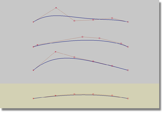
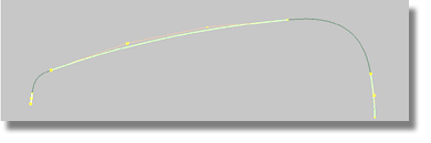
After fitting the three parts of the center line, your curve should resemble the image below.
![]()
Next, blends will need to be created between the three main curves. Another semi automatic tool, the Blend curve, will be utilized to perform this task. Blend curves can be intimidating to the beginner, so for this reason you will be asked to use a limited number of the simpler options.


