A new tool, Object Edit > Align > Align 2008  , will be used to fit a scan
line from the Z-scan layer.
, will be used to fit a scan
line from the Z-scan layer.
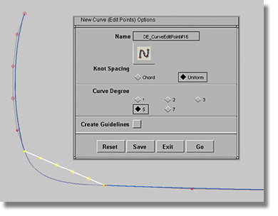
To create a set of curves using edit point curves
 menu item).
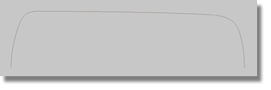
 tool).
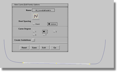
With flat shapes, you may find
it difficult to judge the shape of your curve. To get a better view
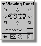
of your work, go to the Viewing Panel by
pressing  +
+  (Windows) or +
  (Mac). Inside
the Viewing Panel, examine the
four icons in the bottom rectangle. Make sure that the box beside
the Perspective option does not contain a check mark. Inside the
bottom rectangle, choose the square icon. You will now be able to
dolly your view in a non-proportional manner that should provide for
a better view of how your curve fits to the scan line.
(Mac). Inside
the Viewing Panel, examine the
four icons in the bottom rectangle. Make sure that the box beside
the Perspective option does not contain a check mark. Inside the
bottom rectangle, choose the square icon. You will now be able to
dolly your view in a non-proportional manner that should provide for
a better view of how your curve fits to the scan line.
To use the icons in the Viewing Panel
+ (Windows) or +  (Mac) and hold down the
buttons.
+ (Windows) or + (Mac) keys. (The Viewing
Panel must remain open to execute the view change).
(Mac) and hold down the
buttons.
+ (Windows) or + (Mac) keys. (The Viewing
Panel must remain open to execute the view change).
 scales the view both horizontally
and vertically, the
scales the view both horizontally
and vertically, the  operates on the horizontal
scale, and the
operates on the horizontal
scale, and the  is reserved for the vertical scale.
Tips for creating a set of curves using edit point curves
 tool.
tool.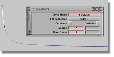
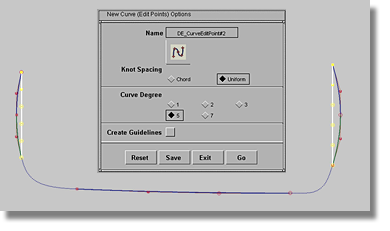
When creating the transition between the front portion of the curve and the middle portion of the curve, use a degree 5 edit point curve to bridge the endpoints.
After completing work
on the Z-scan line, the degree 5 edit point curve looks similar
to the curve used in blending the center line. Note that the current
straight line is not a blend curve. Instead,
it is a degree 5 edit point curve that allows for the use of Object Edit > Align > Align 2008
To use the Align tool for aligning two curves
tool icon to produce the
option box.
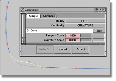
tool options as shown above.
By setting the Continuity option to TANGENT, you will notice that just the first and the second CVs are highlighted in yellow. If you change the Continuity to CURVATURE you will notice that the third CV is highlighted as well.
The Continuity level determines how many CVs are highlighted, or influenced. This knowledge is crucial to understanding the alignment of surfaces later in the tutorial.
The basic concepts behind the primary Continuity settings
Now, it should be clear that in order to achieve curvature continuity on both sides of the curve, a minimum number of 6 CVs is required. Use a degree 5 single span edit point curve to achieve these results.
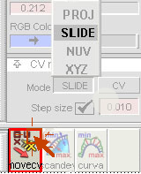
To fit the curve to the scan
line you can now use the SLIDE option
in the CV Move shelf located at the
bottom of the Control Panel. After
sliding a CV, the Object Edit > Align > Align 2008 tool will always bring the
CV back into alignment. By proceeding in controlled steps, you will
achieve a proper deviation.
Also, don’t forget the
possibility of changing the start points of the reference curves.
Click the first CV of the reference curve and move the CV while
pressing  + (Windows) or
  + (Mac) (curve snap) along
the scan line.
+ (Mac) (curve snap) along
the scan line.
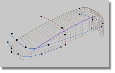
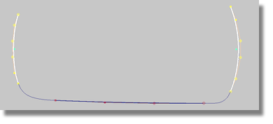
Three additional curves will have to be fitted to the Z-scan lines. The new curves will serve as guides for developing the front end surface and the transition surface. Use the methods previously described in this section to fit the Z-scan lines.
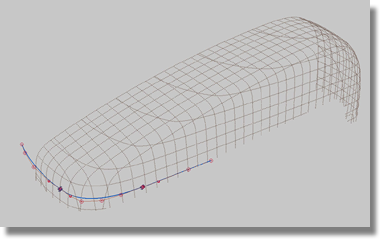
Your completed curves should resemble the image below - the spheres mark the endpoints of the curves.