This type of continuity between curves implies that the endpoints of the curves have the same X,Y, and Z position in the world space. This is the minimum requirement for obtaining G0.
This type of continuity between curves implies that the tangent CVs must be on one line.
This continuity type impacts the third CV of the curve. All three CVs have to be considered in order to maintain a smooth curvature comb.
If a curvature comb does not have a smooth transitional line, further continuity levels can be applied but are outside of the scope of this tutorial. In order to improve the curvature comb, manually modify the position of the three CVs that constitute the G2 continuity.
To change the constraint continuity of a blend point
 > Blend Constraint G2
tool.
> Blend Constraint G2
tool.![]()
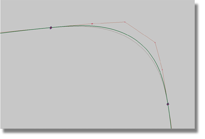
The blend curve changes from a straight line to a smooth transitional curve between the two scanned lines. Note also that the value for Continuity has changed to a 2 (G2) in the Information Window. If the shape of the blend curve is not perfect, you will have an opportunity later in the tutorial to manipulate it.
To examine the proximity of the blend curve to the scan line

The CV distribution of the blend curve is very good, but the blend curve does not fit to the scan line. How could you correct this problem?
Method 1: Change the position of the reference curve endpoints.
Method 2: Use the manipulator to change the shape of the blend curve.
Before you make a decision about how to correct this problem, you should stop to consider some aspects of the work you have completed.
The CV distribution of the blend curve is satisfactory – so, there’s no need to change it. That leaves you with the endpoints – because the top and rear curves still have their construction history, you should use small incremental movements to manipulate the endpoints.
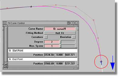
To reactivate a tool’s option box using the Query Edit tool
 tool.
tool.
The Fit Curve Control window and the blue manipulators will appear again.
Because the blend curve is still attached to the curve (with G2), it will follow.
At this point in the tutorial, you should be comfortable with using your eyes to judge the deviation to the scan line. Within the confines of this tutorial, your work does not have to be precise, but for situations where your work must be more professional, you will require the assistance of a measurement tool, such as a Locator.
To use a Locator tool in measuring a curve-to-curve distance
The scan line has to be pickable.
The deviation between the selected items will be measured and appear as a locator.
If you are still not content with the match between the scan line and the blend curve, you can explore another method for reshaping the blend curve.
Blend points are located at the ends of blend curves. Each blend point contains information that can be read in the Information window (Windows > Information > Information window).
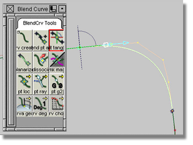
To use the blend curve edit manipulator in the Blend curve toolbox
.
 tool.
tool.
A new manipulator will appear that features a blue sphere and a blue rectangle.
 , pick the sphere, hold down
the mouse button, and move the mouse. Note the movement of the blend
curve.
, pick the sphere, hold down
the mouse button, and move the mouse. Note the movement of the blend
curve.
Up to this point in the tutorial, you have learned two methods for fitting a blend curve to a scan line. The first method changed the reference points. If the first method does not produce sufficient results, as a last resort, use the manipulator to change the shape of the blend curve.
In a real job environment where time is often a critical factor, when changing the connection quality of the blend point to CURVATURE quality (G2) you should simultaneously select both blend points to save time.
Take a moment to consider the work completed at this point in the tutorial.
You will recall that earlier in the tutorial you conducted a deviation control by hand and used your eyes to judge your work.
The next step is to use a curvature comb to check the smoothness of your curve connections.
To check the curvature of curves
 tool.
tool.
Locators will appear that show curvature combs connected to the selected curves. Curvature combs are locators, and as such, you can access information about them through the menu item Windows > Information > Information window.
In most cases though, the curvature comb locator will not provide you with all of the information you may require. To gain more information, select the Curvature shelf from the Control Panel and change the Comb Scale value.
To change the Comb Scale value
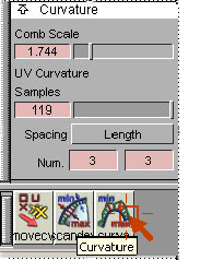
Having changed the Comb Scale and Samples values, your curve should resemble the image below.
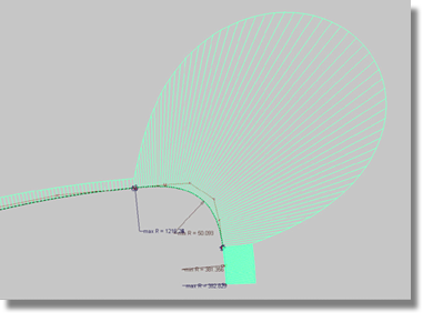
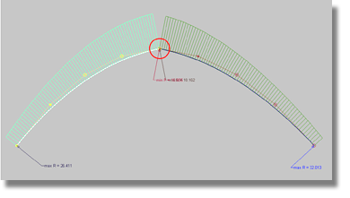
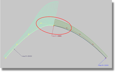
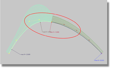
The comb shows a significant jump in values at the position of the blend curves (not a smooth transitional curvature comb). If you were to leave the curves in their current state, the end result would take into account the distortion of values as pointed out by the curvature combs. To remove any curvature distortions you should adjust the combs in a finite fashion. As the manipulation of the curves is a complex task, be careful to adjust the combs in small increments. In fact, it could take you a matter of years to perfect the art of manipulating curves. However, in the interests of time, there are some hints that should speed-up the process.
Factors to consider when manipulating curves
 .
.
The top curve will no longer have a Fit Curve history.
The selected CV will now appear with two arrows that point in the direction of the available movement associated with the CV. The direction will always point toward the next CV.
![]()
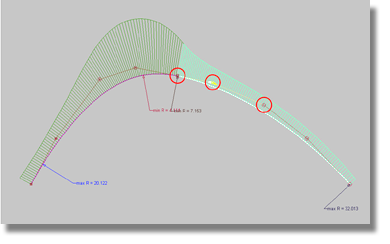
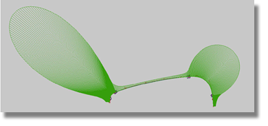
Remember, the objective of this exercise is to strike a balance between a smooth transitional curvature comb and a close fit to the scan lines. As you experiment with different strategies and methods for achieving the desired results, you may find that you will need to correct the endpoints of your first three curves.
Your finished curvature comb should resemble the image below. It may require a significant investment in time to achieve the same results but the experience you gain from the exercise will help you later in your surface modeling career.
 menu item. All of the green
curvature combs should disappear.
menu item. All of the green
curvature combs should disappear.
 to produce a new layer.
 (Windows) or
  (Mac).
 to make all of the Y-sections appear.
At this point in the tutorial, you should have an empty screen.
Following the process detailed at the beginning of the tutorial, you can define the shape of the other two directions (the front surface, or X- scans, and the top surface, or Z-scans).
While fitting the new curves you will be introduced to some new methods. In general though, you will be able to use the same processes detailed in this section to complete the next step.


