


Constructing a Transition
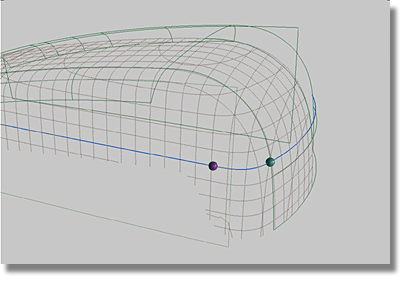
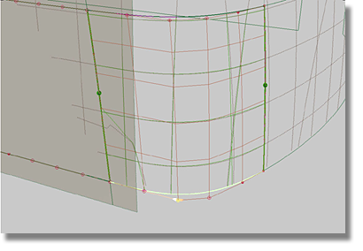
Surface at the Rear of the Model
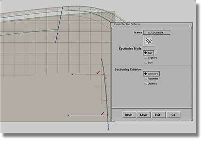
The two spheres act as markers to show the area of the transition surface.
 tool.
tool.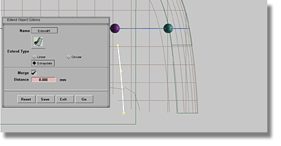
 .
.

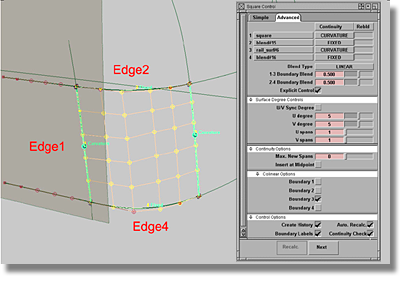
| Set this parameter... | To this value |
|---|---|
| 1 (square) | Set Continuity to CURVATURE, Rebld off |
| 2 (blend #15) | Set Continuity to FIXED, Rebld off |
| 3 (rail_surf#6 | Set Continuity to CURVATURE, Rebld off |
| 4 (blend#16) | Set Continuity to FIXED, Rebld off |
| Blend Type | LINEAR |
| 1-3 Boundary Blend | 0.500 |
| 2-4 Boundary Blend | 0.500 |
| Explicit Control | on |
| U/V Sync Degree | off |
| U degree | 5 |
| V degree | 5 |
| U spans | 1 |
| V spans | 1 |
| Max New Spans | 0 |
| Insert at Midpoint | off |
| Boundary 1 Colinear | off |
| Boundary 2 Colinear | off |
| Boundary 3 Colinear | on |
| Boundary 4 Colinear | off |
| Create History | on |
| Auto. Recalc | on |
| Boundary Labels | on |
| Continuity Check | on |
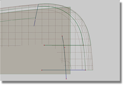
Note that edge # 1 does not utilize the ReBld (Rebuild) option.
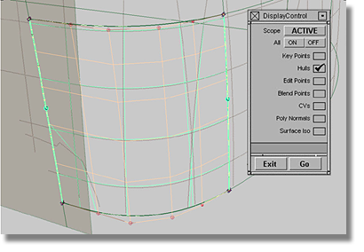
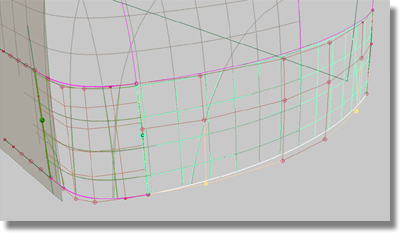
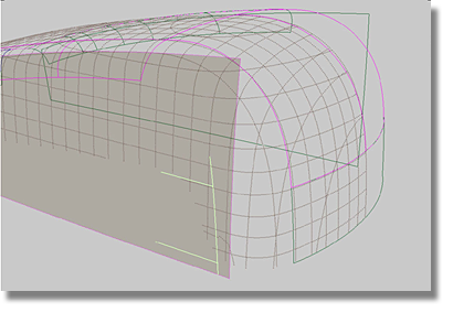
Having completed the transition surface from the rear surface, your model should resemble the image below.
![]()