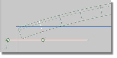
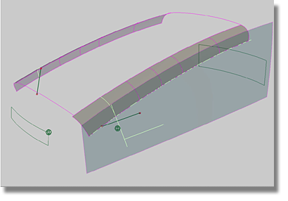
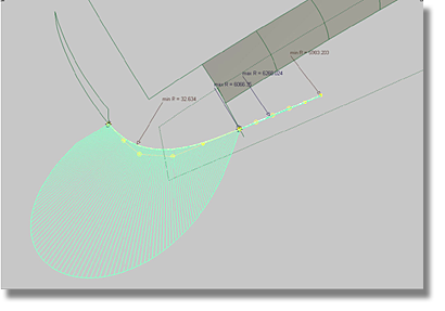
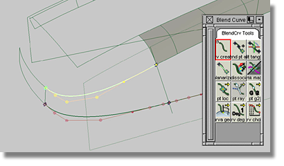
The next step is to model a transition surface that will connect the front surface with the side surface. To begin, determine where the transition surface starts on the side surface by using the fitted Z-curves. In the image below, the spheres at the endpoints of the curve show where the transition has to be placed on the side surface.
To construct the transition surface at the front
![]()
 tool.
tool.
Use the surfaces in the “work” layer. Keep the layer highlighted in yellow so that all new geometry will be assigned to the layer.
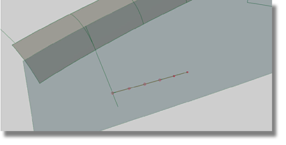
In the image below, use the right-most ball as a guide to where the curve has to be positioned. Eventually, the curve will have to be moved slightly in the X-direction.
 +
+  (Windows) or +
  (Mac) to produce the Viewing
Panel. Ensure that the Perspective view has not been
activated. Click on the side arrow to make sure you are in the side view.
(Mac) to produce the Viewing
Panel. Ensure that the Perspective view has not been
activated. Click on the side arrow to make sure you are in the side view.
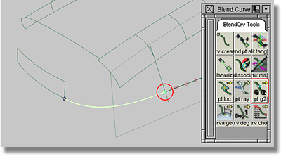
The model should now have a new curve-on-surface that resembles the image below.
To create the transition surfaces
 tool to produce the option box.
In a previous section, you fitted curves to Z-scan lines. The curves created in that section served as guides for establishing the correct Patch Layout. The curves created in this section are designed to serve as the framework of the surfaces. To ensure that the curves created in this section are correct, check the curvature combs of the curves.
To create and modify a curvature comb
 tool.
tool.
 to adjust the density of
the curvature comb.
to adjust the density of
the curvature comb.
 + (Windows) or
  +
+  (Mac)) along the duplicated
curve.
(Mac)) along the duplicated
curve.
To continue with the modeling process, prepare the model for the next required transitional curve.
The fillet surface was
created using the CURVES ON SURFACE setting found
in the Trim Type option of the Surfaces > Surface Fillet  tool. To
avoid confusion when creating the next transitional blend curve,
hide the curve-on-surface using the Object Edit > Query Edit
tool. To
avoid confusion when creating the next transitional blend curve,
hide the curve-on-surface using the Object Edit > Query Edit  tool. The Object Edit > Query Edit tool reproduces the option
box, or control box, of the tool you used to create the selected
surface. In this case, it is the Surface Fillet Control box. In
the control box, change the Trim Type to OFF.
tool. The Object Edit > Query Edit tool reproduces the option
box, or control box, of the tool you used to create the selected
surface. In this case, it is the Surface Fillet Control box. In
the control box, change the Trim Type to OFF.
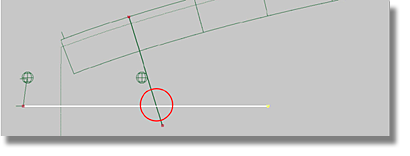
Because you slid the blend point along the curve associated with the side surface, the trim curve of the fillet surface will also have to be moved.
To snap a curve to a pre-defined point
(Windows) or (Mac) and click close to
the blend point).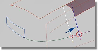
This will change the curve-on-surface on the side surface as well as the curve-on-surface of the fillet surface. The next step will be to create the other transitional curve that will become the foundation for the transitional surface between the side surface and the front surface.
But before creating the
transitional curve, hide the curve-on-surface on the side surface
by using the Object Edit > Query Edit tool.
To use Query Edit to hide the curve-on-surface
tool.
To begin the modification
of the transitional surface, note that the bottom blend curve is
connected to a point inside of the curve on the side surface. For
direct modeling purposes, the current blend curve arrangement is
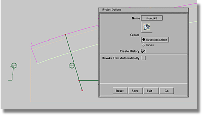
not favorable for modification. To enable alignment using the Object Edit > Align > Align 2008  tool, cut the reference
curve at the point where the blend curve intersects the reference
curve.
tool, cut the reference
curve at the point where the blend curve intersects the reference
curve.
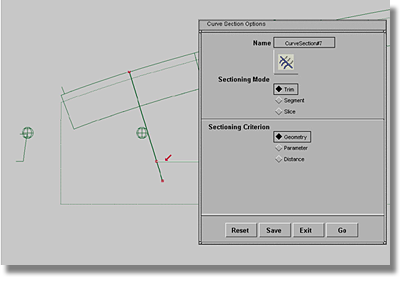
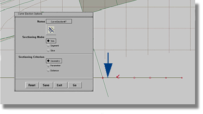
To cut the curve on the side surface and align the transitional curves to the references
 tool.
tool.
| Set this parameter... | To this value |
|---|---|
| Sectioning Mode | Trim |
| Sectioning Criterion | Geometry |
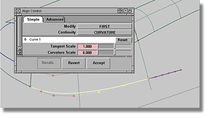
The next step is to align all of the curves to their references by curvature. As a result, all of the former blend curves will gain an additional kind of history that allows CVs to be modeled directly.
tool to produce the option box.
 to view the transition surface.
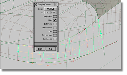
To avoid confusion when selecting curve CVs
 option box.
| Set this parameter... | To this value |
|---|---|
| Scope | ACTIVE |
| Key Points | off |
| Hulls | on |
| Edit Points | off |
| Blend Points | off |
| Poly Normals | off |
| Surface Iso | off |
Although the CVs of the selected surface are hidden, the hulls that act as guides for the CV distribution are still visible. The CVs of the curves are also visible and can be selected without having to navigate a selection window.
To change the fit of the transitional surface by modifying CVs
 .
.
The resulting surface may be flawed if a smooth fit could not be obtained between the transition surface and the scan lines. One factor that could determine the success or failure of the transition is the smoothness of the distribution of the CVs across the transition surface.
If an acceptable result cannot be achieved, increase the degree of your curves to 6.
.
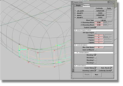
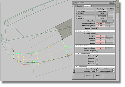
To continue, adjust the degree of the
transition surface. (Remember, by using the Object Edit > Query Edit tool, you can reproduce
the option box of a surface that has a construction history).
To adjust the transition surface
tool.
.
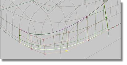
At this point, for each curve you should have one independent (free) CV that is not related to a curvature alignment. The new curves offer more freedom in fitting the transition surface to the scan lines. Within the confines of this tutorial, do not exceed a degree 6 curve. One free CV should be sufficient to maintain a good fit between the transitional surface and the scan lines.
If all CV modifications have been implemented and the results are not satisfactory, change the front surface in the same manner used to create the transitions between the front/rear surface and the top surface.
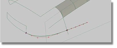
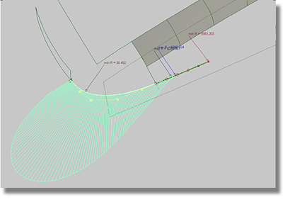
Successful modifications of the model should produce results that resemble the image below.
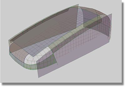
For the next step, try to construct the transition surface at the rear of the model by using the same methods already employed. Reference the images below for tips.


