The ball corner procedure is relatively straight-forward but can be complicated by errors and imbalances created earlier in the model’s construction.
Rules to consider before beginning the ball corner procedure
Up until this point in the tutorial, high-quality model surfaces have been produced from a mathematical point of view. Single span surfaces (except the fillets), called Bezier surfaces, were utilized to guarantee a smooth curvature comb inside of a surface.
The correct use of single
span surfaces requires a high degree of experience with the Object Edit > Align > Align 2008  tool, direct modeling, and
handling Locators.
tool, direct modeling, and
handling Locators.
Because the experience required is outside of the scope of this tutorial, the ball corners created for this model will not use single span surfacing.
How to model a simple ball corner
 tool.
tool.
| Set this parameter... | To this value |
|---|---|
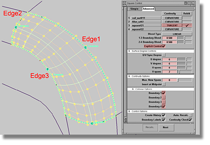
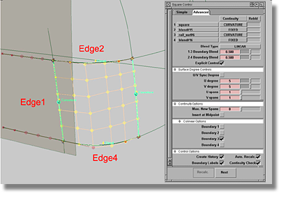
| 1 (rail_surf#5) | Set Continuity to CURVATURE and Rebld off |
| 2 (square#15) | Set Continuity to CURVATURE and Rebld off |
| 3 (fillet_srf) | Set Continuity to CURVATURE and Rebld off |
| 4 (square#14) | Set Continuity to CURVATURE and Rebld on |
| Blend Type | LINEAR |
| 1-3 Boundary Blend | 0.500 |
| 2-4 Boundary Blend | 0.500 |
| Explicit Control | off |
| Max New Spans | 10 |
| Insert at Midpoint | on |
| Create History | on |
| Auto Recalc | on |
| Boundary Labels | on |
| Continuity Check | on |
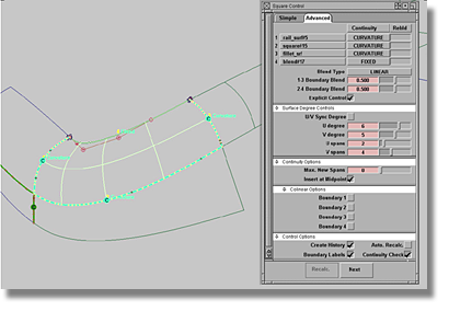
| Set this parameter... | To this value |
|---|---|
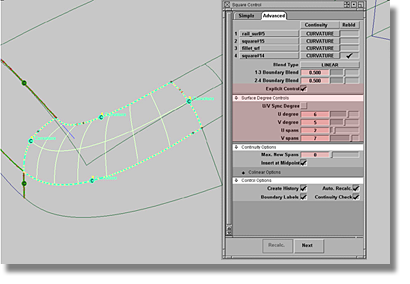
| 1 (rail_surf#5) | Set Continuity to CURVATURE and Rebld off |
| 2 (square#15) | Set Continuity to CURVATURE and Rebld off |
| 3 (fillet_srf) | Set Continuity to CURVATURE and Rebld off |
| 4 (square#14) | Set Continuity to CURVATURE and Rebld on |
| Blend Type | LINEAR |
| 1-3 Boundary Blend | 0.500 |
| 2-4 Boundary Blend | 0.500 |
| Explicit Control | on |
| U/V Sync Degree | off |
| U degree | 6 |
| V degree | 5 |
| U spans | 2 |
| V spans | 7 |
| Max New Spans | 0 |
| Insert at Midpoint | on |
| Create History | on |
| Auto. Recalc | on |
| Boundary Labels | on |
| Continuity Check | on |
There may be slight differences in the appearance of your model and the model depicted in this tutorial. For this reason, you should explore the Square Control box to find the best possible arrangement for your surface.
Judge the surface by using an evaluation tool that shows you the stripes as projected by a lamp onto selected surfaces. Try moving the lamp using the blue, green, and red manipulators to find a lighting arrangement that best accentuates your model.
 tool to open the option
box.
tool to open the option
box.
| Set this parameter... | To this value |
|---|---|
| Type of Bands | Multiple |
| Repeat Multiple Bands | 25 |
| Shaded surface | on |
| Visual Curves | off |
| Blur | 0.0100 |
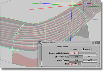
At
this point in the modeling process, the front-end of the model is
complete. However, if you are not satisfied with the results presented
by the Evaluate > IsoAngle tool, modify the ball corners
using the direct modeling method. When direct modeling the ball
curve, the number of CVs will have to be reduced, which in turn,
will reduce the number of spans.
 .
tool.
.
tool.
| Set this parameter... | To this value |
|---|---|
| 1 (rail_surf#5) | Set Continuity to CURVATURE and Rebld off |
| 2 (square#15) | Set Continuity to CURVATURE and Rebld off |
| 3 (fillet_srf) | Set Continuity to CURVATURE and Rebld off |
| 4 (blend#17) | Set Continuity to FIXED and Rebld off |
| Blend Type | LINEAR |
| 1-3 Boundary Blend | 0.500 |
| 2-4 Boundary Blend | 0.500 |
| Explicit Control | on |
| U/V Sync Degree | off |
| U degree | 6 |
| V degree | 5 |
| U spans | 2 |
| V spans | 4 |
| Max New Spans | 0 |
| Insert at Midpoint | on |
| Create History | on |
| Auto. Recalc | off |
| Boundary Labels | on |
| Continuity Check | on |
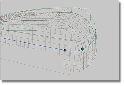
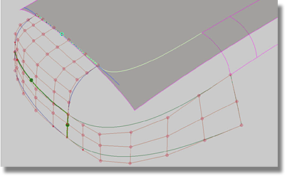
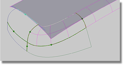
The newly created square surface has no connection to the top surface.
 tool to produce the options
box.
tool to produce the options
box.
| Set this parameter... | To this value |
|---|---|
| Find | Positional Continuity |
| Check Spacing by | # Per Span |
| Locator Persistence | on |
| Check Interior | on |
| Show Max Labels | on |
| Show Edge Labels | on |
| Show Comb | on |
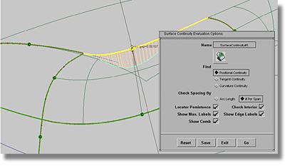
The results from the Evaluate > Continuity > Surface Continuity tool show a small gap between
the surface edge and the curve-on-surface. The surface will need
to be aligned to the curve-on-surface.
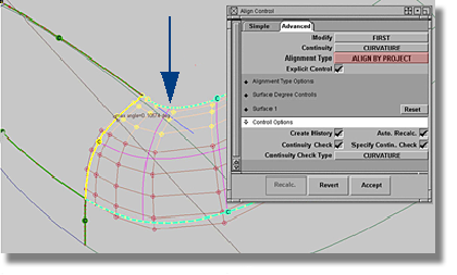
To align the surface with the curve-on-surface
.
tool to produce the options box.
| Set this parameter... | To this value |
|---|---|
| Modify | FIRST |
| Continuity | CURVATURE |
| Alignment Type | ALIGN BY PROJECT |
| Explicit Control | on |
| Create History | on |
| Auto. Recalc | on |
| Continuity Check | on |
| Specify Contin. Check | on |
| Continuity Check Type | CURVATURE |
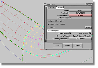
It is possible that
the alignment procedure will destroy the curvature continuity between
the ball corner surface and the front-end transitional surface. To
correct this problem, use the Object Edit > Align > Align 2008 tool again to restore the
broken curvature connection. Before attempting another alignment,
delete the construction history of the first alignment. The
second alignment process could damage the results of the first alignment
process; in this case, set the Continuity option
to TANGENT instead of CURVATURE.
If the alignment remains damaged after restoration attempts, a work-around
can be executed.
A work-around for restoring a broken curvature connection
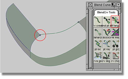
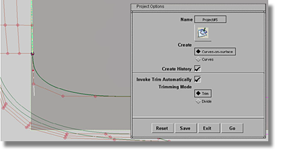
The
mathematical behavior of a curve-on-surface derived from the Surface Edit > Create CurvesOnSurface > Project  tool differs from a curve-on-surface derived
from the Surface Edit > Create CurvesOnSurface > Project normal tool.
tool differs from a curve-on-surface derived
from the Surface Edit > Create CurvesOnSurface > Project normal tool.
normal tool.
Project the ball corner edge onto the top surface to produce a new
curve-on-surface, complete with a new mathematical behavior.
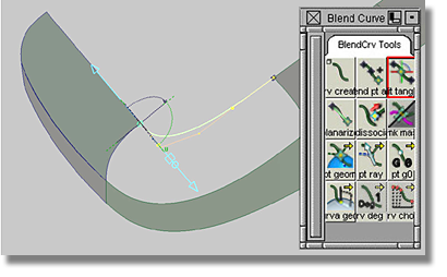
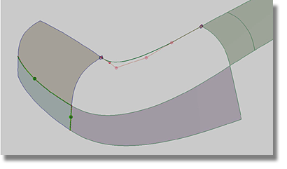
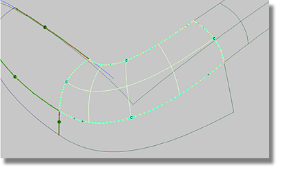
The last possibility to adjust the alignment of the ball corner is to directly manipulate CVs.
Begin by aligning the ball corner to the top surface.
Then, generate a TANGENT Continuity between the ball corner and the front-end transitional surface by using the PROJ (project) option in the Control Panel > Evaluate > Move CV tool.
Before you modify the CVs by hand, you must delete the construction history.
The end result of this exercise should be a balled corner with less spans than those created by the curve-on-surface used in the construction of the initial square.
To finish the rear ball corner
To create a square surface,
use the edges of the transition surfaces, the fillet surface, and
a curve-on-surface. Once you have a new square surface, experiment
with the various options of the Surfaces > Boundary Surfaces > Square  tool to find the best possible
CV distribution.
tool to find the best possible
CV distribution.