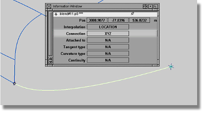
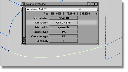
To gain access to the
information contained within a blend curve, use the Windows > Information > Information Window  menu item after selecting
an associated blend point.
menu item after selecting
an associated blend point.
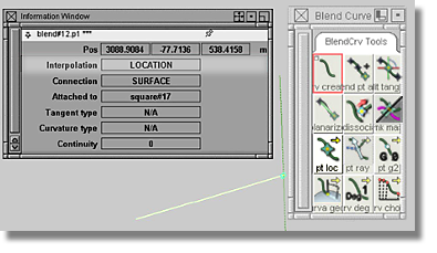
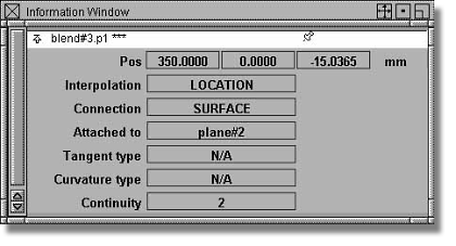
Primary options presented in the Information Window
This
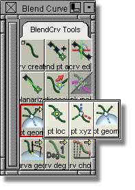
tool set allows the user to specify a direction type that determines
how a blend curve passes through a blend point. For surface modelers,
the BlendCrv Tools > Constraint Interpolation Direction  > Blend Constraint
Interp Geometry tool is of particular interest. This
tool aligns the blend curve to the reference geometry using a PARAMETRIC Curvature
type that results in a similar curvature alignment to
that achieved with the Object Edit > Align > Align 2008
> Blend Constraint
Interp Geometry tool is of particular interest. This
tool aligns the blend curve to the reference geometry using a PARAMETRIC Curvature
type that results in a similar curvature alignment to
that achieved with the Object Edit > Align > Align 2008  tool.
tool.
The LOCATION setting
is the Interpolation default for each
new blend curve. The
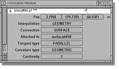
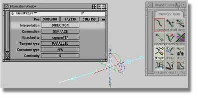
other Interpolation settings, DIRECTION and GEOMETRY, each
offer a manipulator that can be accessed via the BlendCrv Tools > Blend Curve Edit  tool.
tool.
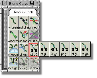
The Interpolation type can be changed by using the highlighted buttons in the images below.
This setting forces the blend curve to pass through the blend point's location in space.
This setting forces the blend curve to pass through the blend point's location in space while travelling in a dictated world space direction.
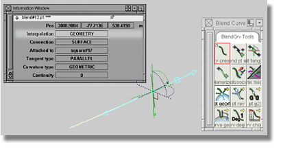
This setting forces the blend curve to pass through a point on a curve or surface and travel in a direction relative to a curve or surface.
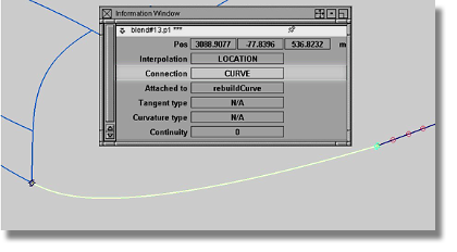
The Tangent type option specifies a direction that dictates how a blend curve relates to blend point(s).
There are two Tangent types that are defined using the Constraint Interpolation Direction tool found in the blend curve toolbox.
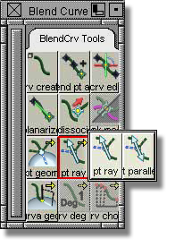
Blend constraint directed (pt ray): sets an actual direction for the curve tangent. Use this Tangent type when the specific tangent direction at the location of the blend point is important.
Blend constraint parallel: sets a line along the curve that passes (in either direction) through the blend point. This option is easier to enforce and results in a better curve continuity.
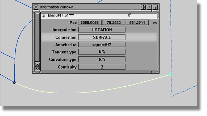
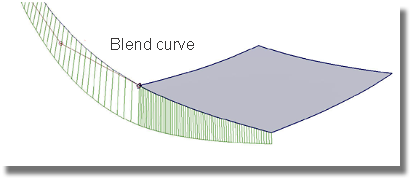
This option is an important component of blend points when blend curves are attached to a surface.
There are two curvature types available, PARAMETRIC and GEOMETRIC.
This type of
curvature is similar in behavior to the Object Edit > Align > Align 2008 tool. In general, when attaching
a blend curve with PARAMETRIC curvature to a surface,
the result will appear similar to that achieved by aligning a blend
curve to the isoparametric direction of a surface.
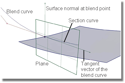
This type of curvature draws upon a plane constructed from the surface normal at the blend point and the tangent vector of the blend curve. By intersecting the plane with the surface, a section curve can be created that will allow for the alignment of the blend curve.
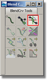
This option defines the quality of the blend curve as it passes through the point in space associated with the blend point.
Continuity types, G3 and G4, require the automatic insertion of additional spans to the blend curve. Usually, G2 Continuity is sufficient for meeting the requirements of a surface modeling project.
To set the Continuity type, the blend point must be selected. As detailed in the image below, use the highlighted tool found in the blend curve toolbox to change the Continuity type.