A detailed examination of the tools required to perform a global evaluation of the finished model.
When importing or exporting a surface model, check that the model meets the required continuity. The model can be evaluated for all three continuity types (POSITION, TANGENT, and CURVATURE).
The entire model must
be selected before an evaluation can be conducted. To begin the evaluation,
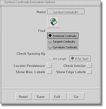
double-click the Evaluate > Continuity > Surface Continuity  tool icon to produce an
option box. The model can be evaluated using the three settings
associated with the Find option (Positional Continuity,
Tangent Continuity, and Curvature Continuity).
tool icon to produce an
option box. The model can be evaluated using the three settings
associated with the Find option (Positional Continuity,
Tangent Continuity, and Curvature Continuity).
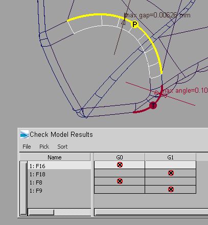
As highlighted in the image below, the Surface Continuity Evaluation Options box allows for the selection of specific errors to be returned by the evaluation process.
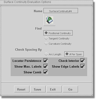
The evaluation process is executed via the Go button located at the bottom of the options box.
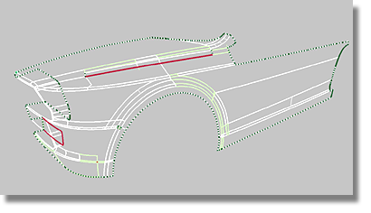
The model is evaluated according to the stated construction tolerances. If there are errors in the model, they are highlighted on the model.
The outline of the model shell appears as a green dotted line. Interior gaps, or Tangent Continuity and Curvature Continuity errors, are highlighted in red.
 tool, the locators disappear.
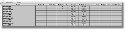
When exporting a model to an external CAD package, special requirements must be addressed in terms of the mathematical behavior of the geometry. The Evaluate > Check Model tool offers additional capabilities for evaluating the geometry of a model. At the top of the Check Model Settings option box, the Check, Objects and Report options offer settings for refining the organization of the algorithms to be evaluated.
By pressing the Check button at the bottom of the Check Model Settings box, the evaluation process is enabled. The results of this evaluation are populated into the Check Model Results table. Clicking the items listed in the Check Model Results table highlights the corresponding objects in the model scene.
Within the Check Model Settings box, under the Check Model Parameters chapter, the model can be evaluated for the presence of multi knots by simply enabling the Multiple Knots option. By also enabling the Internal Tangent Discontinuity option, tangent breaks are evaluated that occur inside of a surface that contains multi knots.
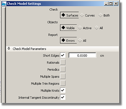
By enabling the Short Edges and Maximum Degree options found in the Check Model Settings option box, the model can be checked for short edges and geometry exceeding the maximum degree specified. When the Short Edges and Maximum Degree options are enabled, the fields to the right of their check boxes allow for the manual input of values.
The Short Edges evaluation will detect all surfaces that have edges (including trimmed edges) shorter than the distance specified in the tolerance field to the right of the check box. The evaluation of short edges is crucial to ensuring a smooth transition to an external CAD system.
The Maximum Degree evaluation option will detect all curves and/or surfaces that have a higher degree than that specified in the field to the right of the check box.
Some CAD systems experience issues when importing and handling rational geometry. To better facilitate the transition of the model to an external CAD system, the Periodics and Rationals options are available to the modeler.
There is no method for
changing rational geometry into non-rational geometry without losing
the shape of the geometry. However, the creation of rational geometry
can be avoided by adjusting the options found in the Rational Flags
chapter located within the Modeling modes chapter of the Preferences > Construction Options  menu item.
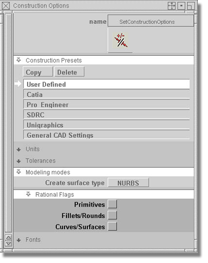
When the three options located within the Rational Flags chapter are not enabled, Surface will always create non-rational geometry.
In addition to problems associated with rational geometry, some CAD systems experience issues with the importing and handling of periodic geometry. To address these issues, enable the Periodics option found in the Check Model Parameters chapter of the Check Model Settings option box. Surfaces and curves of a revolutionary character may be considered periodic geometry. A method for changing their behavior is to detach the geometry from the items and create a beginning point and an ending point.
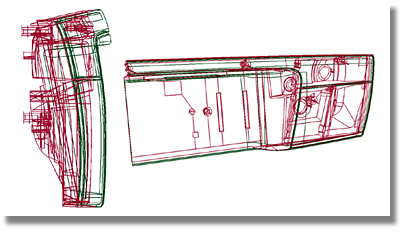
The Evaluate > Dynamic Section  tool moves a set of sections
through a surface model. (As depicted in the image below, it
is possible to add a curvature plot to the section set). Begin the
dynamic evaluation by selecting the entire model.
tool moves a set of sections
through a surface model. (As depicted in the image below, it
is possible to add a curvature plot to the section set). Begin the
dynamic evaluation by selecting the entire model.
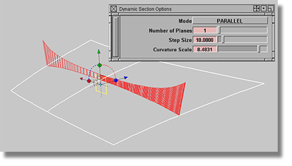
A manipulator that has the same functional characteristics as the construction plane manipulator allows for the modification of the section set. Once the Dynamic Section tool has been enabled, two buttons will appear at the bottom of the screen.
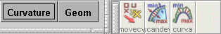
Pressing the Curvature button creates a curvature plot on the section set while pressing the Geom button temporarily changes the section set into a curve.
When attempting to evaluate an intricate model, it can be bothersome to focus on one section set if the model is cluttered with overlapping lines.
The View > Adjust Clipping Plane  tool offers a solution for
reducing visual clutter by using one window to influence the display
depth of another.
tool offers a solution for
reducing visual clutter by using one window to influence the display
depth of another.
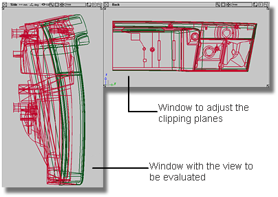
In order to use the Clipping Plane tool, there must be a minimum of two windows open in the scene. One window will act as the clipping plane instrument (on the right in the above image) while the other will be the affected window (on the left in the image above).
To begin the clipping plane procedure, make sure that the affected window has the current window focus (bordered in white). After clicking the Clipping Plane tool, the focus will then shift to the window that will be used to perform the procedure.
In the window that acts as the clipping instrument, there will be two clipping planes, the near and the far.
Using the  , click the left-hand edge
of the window that is functioning as the clipping instrument. A
solid black line appears that represents the near clipping plane.
, click the left-hand edge
of the window that is functioning as the clipping instrument. A
solid black line appears that represents the near clipping plane.
In order to produce the
far clipping plane, use the  to click the right-hand
window edge. The far clipping plane is represented by a black dotted
line.
to click the right-hand
window edge. The far clipping plane is represented by a black dotted
line.
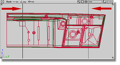
To adjust the far clipping
plane, drag the . To adjust the near clipping plane,
drag the l . By using a combination
of near and far clipping planes, the visibility of the geometry
can be manipulated in the affected window.
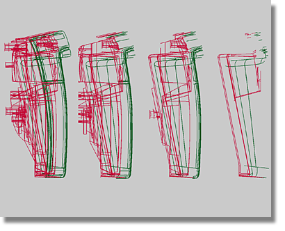
The image below depicts a sequence of views that can be achieved by moving the clipping planes through a model.
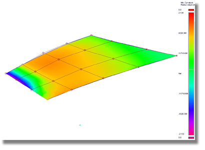
To meet manufacturing requirements, it is necessary to evaluate a surface model for the minimum radii size. All radii that fall below a defined value must be detected.
To evaluate the minimum radii, use the Curvature Evaluation shader found in the Diagnostic Shading chapter located in the Control Panel. By clicking the icon highlighted in the image below, the Surface Evaluation chapter is produced. There are eight settings in the Type lister.
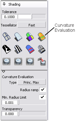
The Princ. Max setting of the Type option shows the Min. Radius Limit option. Turning on this option by clicking the checkbox displays a slider that can be used to enter a minimum radius value.
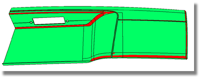
In the image below, the surfaces, or areas of surfaces that fall below the defined minimum radius limit are highlighted in red.
Because CVs (Control Vertices) represent surfaces and curves, their distribution provides a good method for evaluating the quality of a shape.
Each corner, or end point, features one CV. This lone CV is the smallest representation of a planar surface or line. By adding more CVs, the flexibility of the geometry object is increased.
A shaped object has a CV blanket, or CV net, located above the surface or curve. The CVs are the knot points in the net. A complete row of CVs are referred to as a Hull.
The number of CVs is referred to as the Degree of CVs.
Degree = (total number of CVs in one direction) - 1
The highest Degree that a geometry object can obtain in Surface is 9.
CVs can be turned On (+) or Off (-) via the Control Panel after the geometry has been selected.
The appearance of CVs
can be altered via the ObjectDisplay > Draw Style  menu item.
To evaluate the distribution
of CVs, use the View > Local Move Camera > Azimuth/Elevation  tool or the View > World Move Camera > Dolly
  tool in a non-perspective
window.
tool in a non-perspective
window.
Basic rules of CV distribution
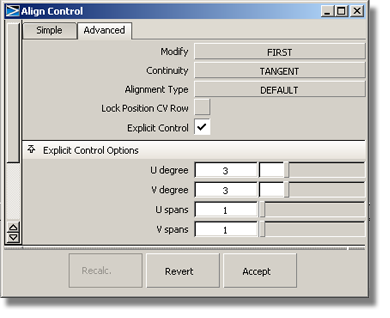
Various tools in Surface offer an Explicit Control option.
This option allows for the manipulation of the number of spans and the degree of created or modified surfaces. Enabling the Explicit Control option produces an Explicit Control Options chapter that regulates the degree and number of spans.
When working without the Explicit Control option enabled, Surface usually calculates more spans then are necessary. There are, however, some default settings within Surface that calculate degree 3 geometry instead of degree 5 when the Explicit Control option is not enabled.
The image below shows a square surface that was created without the Explicit Control option enabled.
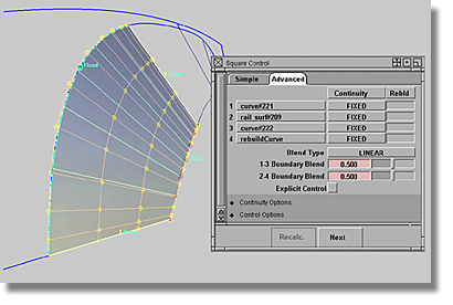
As is often the case, the mathematical complexity of a curve-on-surface unnecessarily increases the number of spans on a created or aligned geometry.
The image below shows the same surfacing situation as the image above, but with the Explicit Control option enabled.
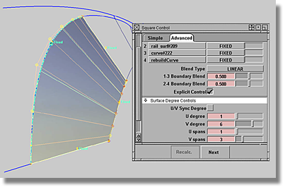
Another benefit of enabling the Explicit Control option is the regulation of an even span distribution.
The image below shows the span distribution that results from not enabling the Explicit Control option.
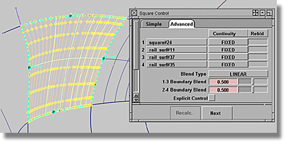
As can be seen in the image above, the distances between the spans varies, resulting in a span distribution that is not regular.
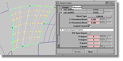
The image below shows the results of the same surfacing situation as the above image, but with the Explicit Control option enabled. As well as decreasing of the number of CVs, the span distribution is of a higher caliber of regularity than the image above.
Diagnostic Shading via the Control Panel
Curvature diagnostics are enabled by clicking the Curvature Evaluation shader icon found in the Diagnostic Shading chapter in the Control Panel.
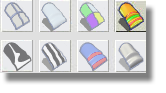
By clicking the highlighted icon in the image above, the Curvature Evaluation chapter is produced. The image below shows the expanded Curvature Evaluation chapter.
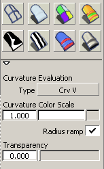
A variety of evaluation settings are available by clicking the button associated with the Type option.
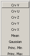
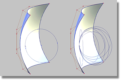
The Curvature Type settings listed in the image above calculate the curvature of surfaces on each point. This calculation measures the diameter of a circle that touches the surface at each point. Points that have a circle with the same diameter will be have the same color. The image below demonstrates that each point can have several circles. The evaluation Type settings specify which circles will be used for the calculation.
The Crv U and Crv V settings orient the circle of each point in the U/V direction.
The Crv X, Crv Y, and Crv Z settings orient the circle of each point in the X, Y, and Z direction.
The Gaussian setting multiplies the value of the smallest circle and the value of the largest circle. Areas where the surface has inflections or holes can be easily detected by examining the accompanying color bar for negative radius values. The color bar is available at the radius ramp (red - green - blue - purple) that is activated in the Diagnostic Shading chapter located in the Control Panel.
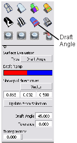
Draft Angle shading is enabled by clicking the Surface Evaluation shader icon found in the Diagnostic Shading chapter in the Control Panel.
The Draft Angle Type setting isolates which parts of a surface are in-draft and which parts are out-of-draft for a specified pull vector and draft angle. The results generated from the Draft Angle Type setting depict in-draft points in blue, and out-of-draft points shaded in red. A tolerance region can also be applied to the model, the results of which are shaded in pink. The Draft Angle Type settings work best when each normal of the selected surface set points in the same direction, either inwards or outwards.
 tool.
tool.
In order to evaluate
how the surface set relates to the pull vector, the pull vector
must first be selected. Usually the pull vector is defined by a
linear curve. By using the Construction > Vector  tool, it is possible to
create a vector based on the curve. Select the vector, then click
the Update From Selection button
in the Control Panel to use this vector. The Vector/Rotation values
in the panel are automatically updated.
tool, it is possible to
create a vector based on the curve. Select the vector, then click
the Update From Selection button
in the Control Panel to use this vector. The Vector/Rotation values
in the panel are automatically updated.
Another method is to
use the Evaluate > Parting Line tool.
tool’s icon to open the
option box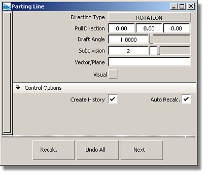
Direction Type Vector: set the Direction Type option to VECTOR and type the three vector coordinates into the Pull Direction field
Direction Type Rotation: set the Direction Type option to ROTATION and type the three angle values for the vector into the Pull Direction option
Vector/Plane: in the Vector/Plane option, type in the name of a vector, or select a vector in the scene.

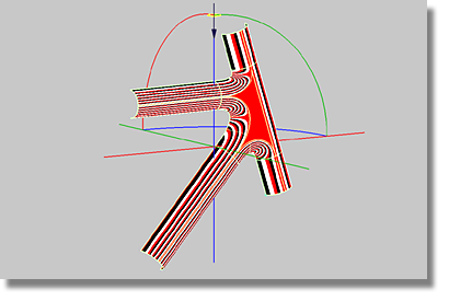
The optimal method is Method 3 when selecting the pull direction vector directly in the scene. Begin the procedure for Method 3 by first placing the cursor in the field associated with the Pull Direction option.
The next step is to select the vector in the scene which will populate the Pull Direction option with the vector coordinates.
The Draft Angle calculation executed in the Diagnostic Shading chapter of the Control Panel uses the Pull Direction value specified in the Parting Line option box.
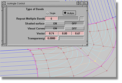
The Evaluate > IsoAngle  tool is employed to evaluate
a surface set by highlighting the surface with a light source.
tool is employed to evaluate
a surface set by highlighting the surface with a light source.
By means of a light source manipulator, surfaces can be evaluated using a variety of lighting arrangements. When compared to the results generated with the Horizontal/Vertical shader located in the Control Panel, the IsoAngle tool produces a wider range of evaluation.
To use the IsoAngle tool, begin by selecting the surfaces to be evaluated. Then, after opening the option box, the shading and the light source manipulator will appear.
By setting the Shaded surface option to OFF and Visual Curves option to ON, the highlights produced by the light source will appear as visual curves. By offering a permanent highlight control, this arrangement is very beneficial when evaluating directly modeled surfaces.
To remove the visual lines, reselect the surface and set the Visual Curves option to OFF.


